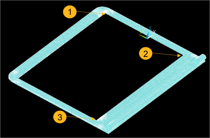
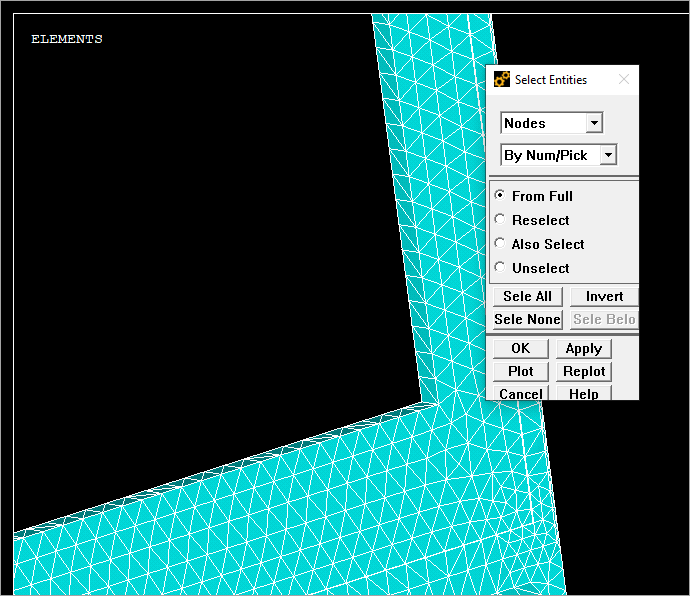
This alternative approach avoids using an External Model in Workbench. After the Mechanical APDL application reads the original .cdb file, you have the option to select three points in the mesh from the injection molding data. The following example selects three nodes of the geometry, and uses the NLIST command to get their coordinates:
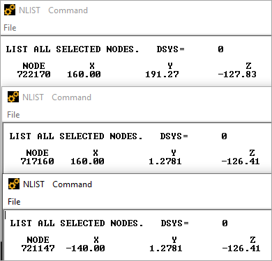
Important: Write the coordinates down in your notes to use later in the Ansys Discovery application.
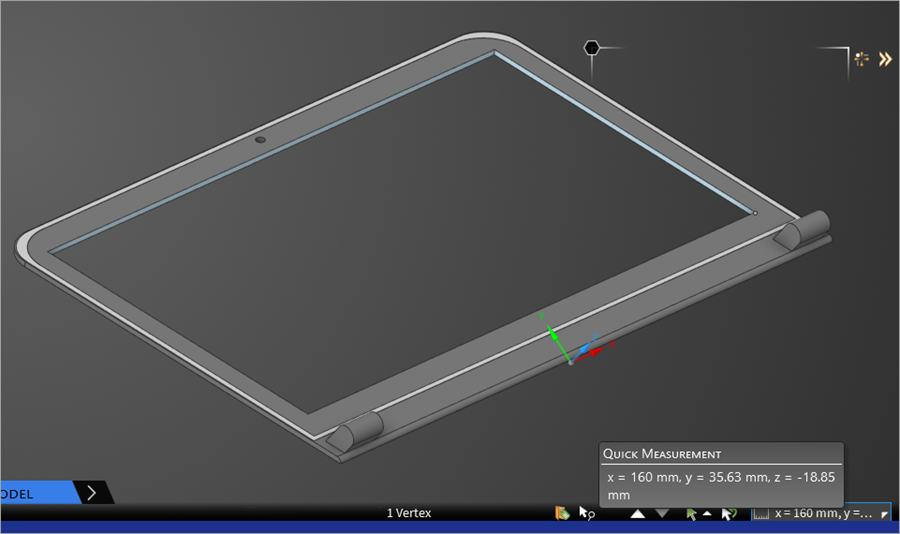
In the Discovery application, you must select the corresponding points in the target geometry, and identify the coordinates as shown in the image below.
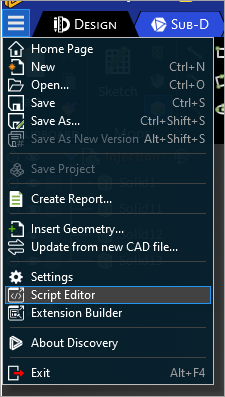
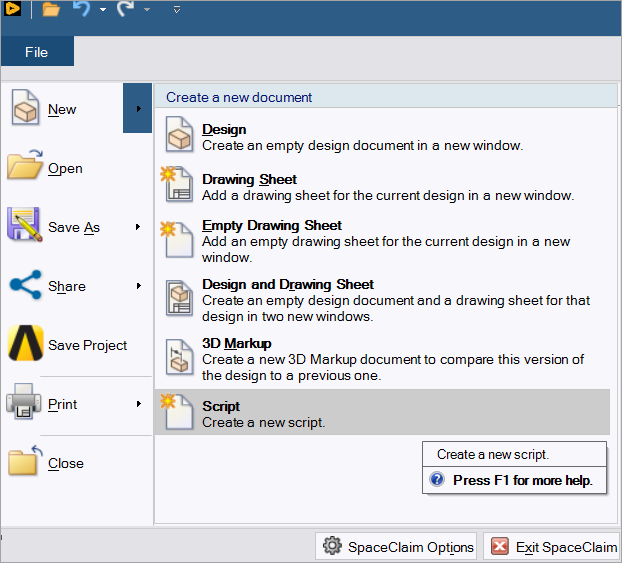
Next, go to the File tab or the three line icon in the menu of both tools, and select either Script Editor or New > Script respectively.
Use a script like the one given on the developer portal to interact with the geometry environment.
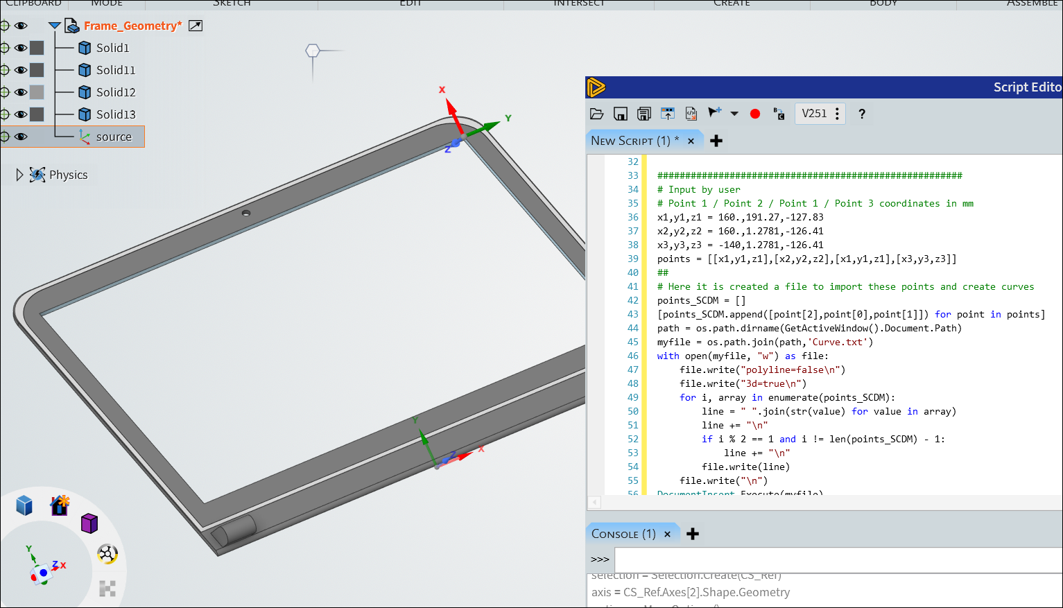
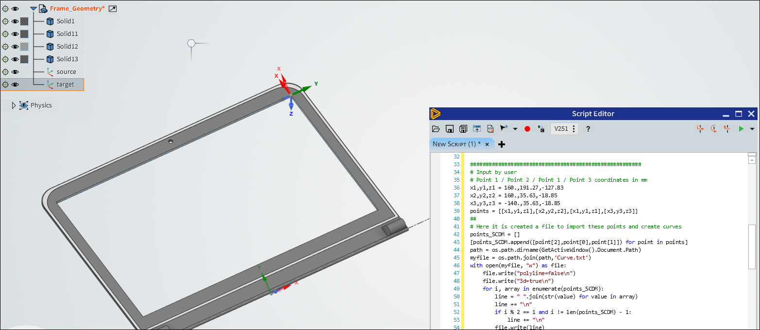
Now, you must replace x1,y1,z1,x2,y2,z2,x3,y3,z3 with the coordinates from the NLIST command for source and with the coordinates given by Discovery, as shown in the screen captures below.
These respective coordinates create the source and target coordinate systems that transfer to the Mechanical application.