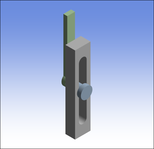
This section demonstrates the steps to assemble a geometry using a three-part a pendulum joint model. The Assemble feature enables you to assemble the different parts of a model and then "set" the assembled configuration for the start of your analysis. The geometry shown below was imported into a Rigid Dynamics analysis system.
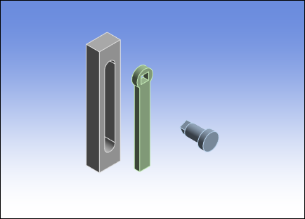
As illustrated, the geometry consists of three bodies, including (from left to right) the Basis, the Arm, and the PendulumAxis. These three bodies have been imported completely disjointed/separate from each other.
The first step to orient and assemble the bodies is to add a Body-Ground Fixed joint to the body named Basis. To do this:
Select the Connections object.
From the Connections Context tab, open the drop-down menu and select .
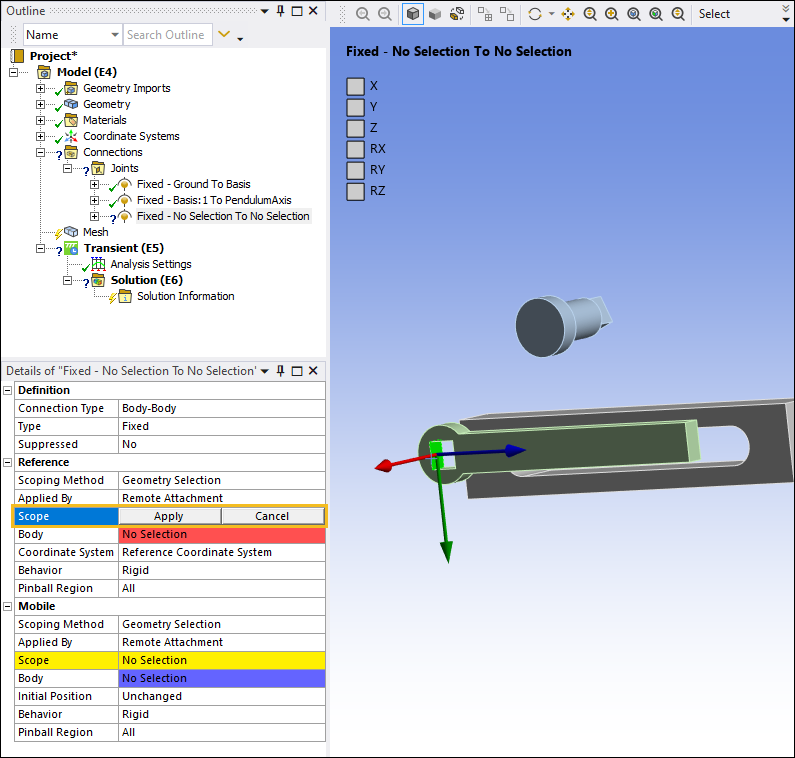
Select the flat external face on the Basis body as shown below. In the Details pane under the Mobile category, select the field of the Scope property and then select .

Next, you need to join the PendulumAxis body to the Basis body. Since they are initially disjoint, you need to set two coordinate systems. One for each body. Additionally, to fully define the relative position and orientations of the two bodies, you must define a fixed joint between them. To do this:
From the Connections Context tab, open the Body-Body drop-down menu and select .
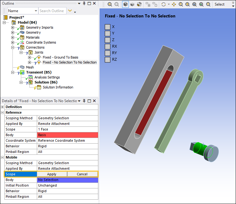
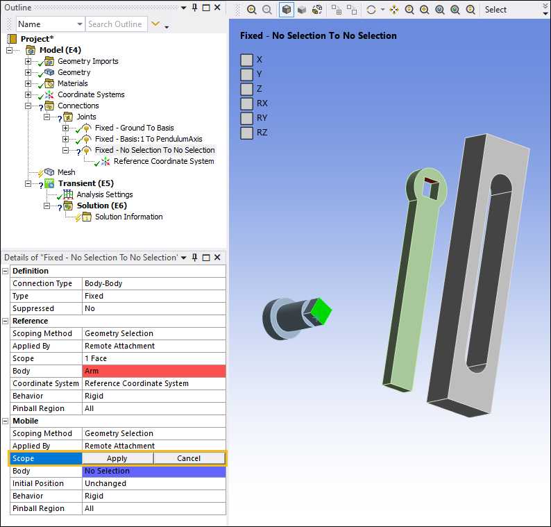
Highlight the face on the Basis geometry as shown below. In the Details pane, select the field of the Scope property under the Reference category, and then select .
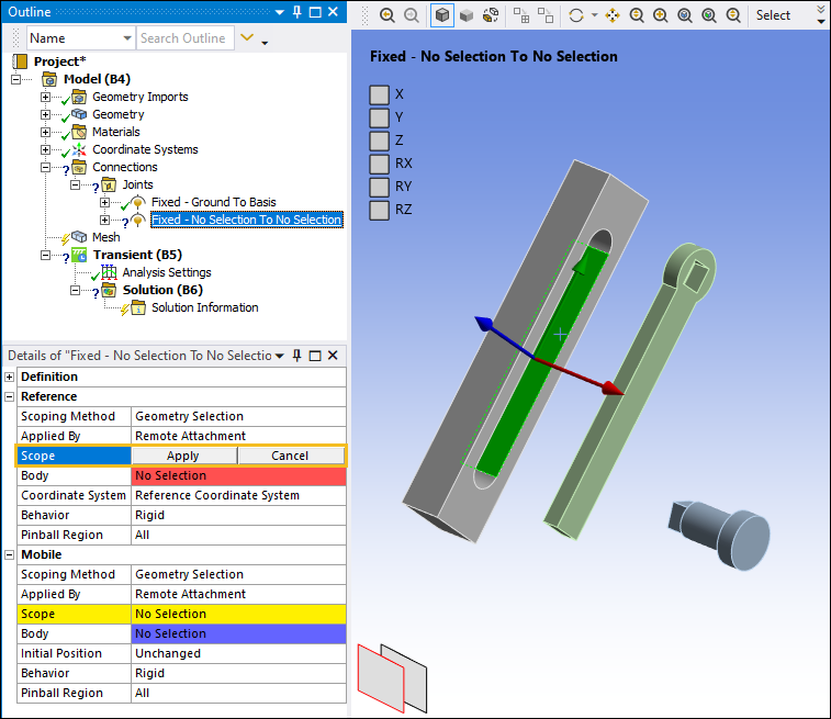
Select the cylindrical face of the PendulumAxis as shown below. In the Details pane, select the field of the Scope property under the Mobile category and then select Apply.
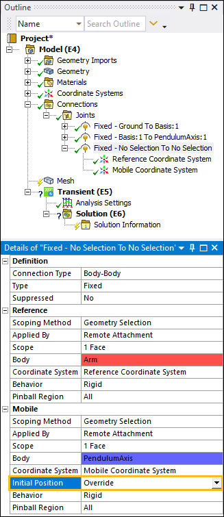
Note: The above joint was renamed using the context (right-click) menu option . This is done throughout the example.
Set the Initial Position property to .
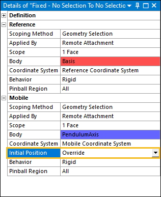
The joint has two coordinate systems associated with it: a Reference and a Mobile coordinate system. You now need to associate the Reference Coordinate System and the Mobile Coordinate System to the respective bodies with the appropriate orientations. To associate the Reference Coordinate System to the respective bodies:
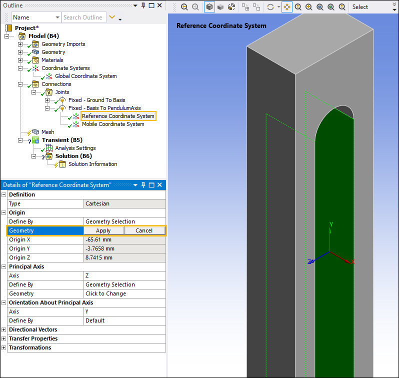
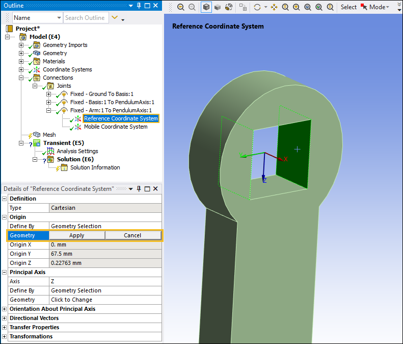
Expand the Fixed - Basis To PendulumAxis joint object, select the Reference Coordinate System object, and then select the field of the Geometry property.
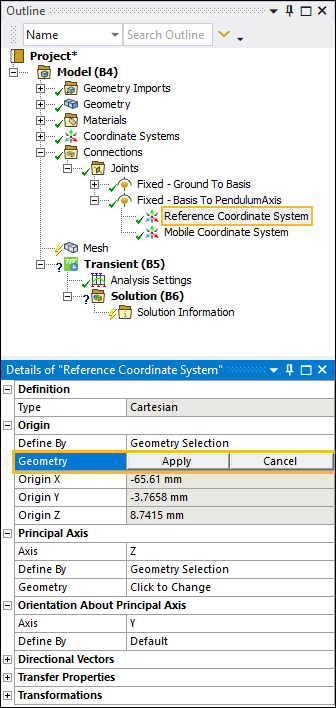
Select the two internal rectangular faces on the Basis body as shown below. Select the field of the Geometry property and then select Apply. This places the Reference Coordinate System at the center of the opening.
To associate the Mobile Coordinate System to the respective bodies:
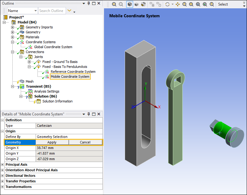
Select the Mobile Coordinate System object. This coordinate system is currently associated with the Basis body. In the Details pane, under the Origin category, select the field of the Geometry property, select the cylindrical surface on the PendulumArm body as shown below, and then click .
Next, you need to correctly orient the PendulumAxis coordinate system:
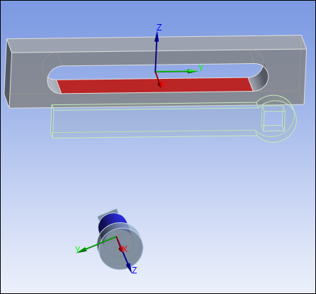
With the Mobile Coordinate System object still selected, under the Principal Axis category, select the field of the Geometry property, select one of the vertical edges on the PendulumAxis body such that the Z axis is parallel to the edge as shown below, and then click .

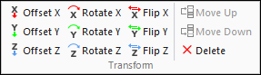
With Mobile Coordinate System object still selected, select the Offset X option from the Transform group of the Coordinate Systems Context tab.
Under the Transformations category, set the Offset X property to
2.5mm to align the faces of the PendulumAxis body with the Basis body.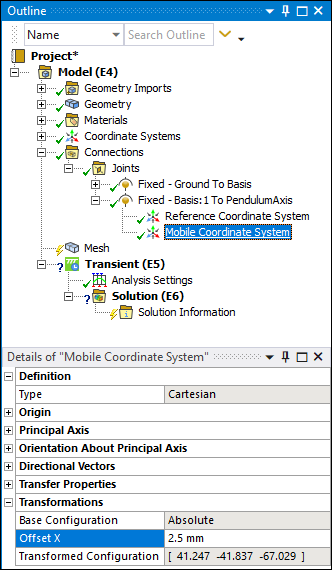
Note: Transformations enable you to manipulate the coordinate systems by entering offsets or rotations in each of the three axes.
The coordinate systems should appear as follows.
Next, you need to define the coordinate systems to join the Arm body to the PendulumAxis body.
Insert a new joint. From the Joint group on the Connections Context tab, select Body-Body > .
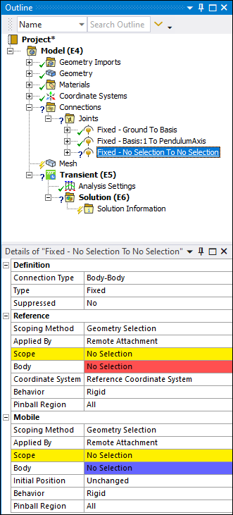
Define the scoping of the Reference side. Select one of the faces of the Arm, as illustrated below, that will connect to the PendulumAxis, and then select .
Specify the Scope property of the Mobile category by selecting the flat end face of the PendulumAxis as shown below, select the field of the Geometry property, then click .
Set the Initial Position under the Mobile category to .
Set the origin of the Reference Coordinate System to the center of the hole in the Arm. Select the Reference Coordinate System object. Select the two side faces from the hole in the Arm, and under the Origin category, select the field of the Geometry property, then click .
Next, you will need to offset the Coordinate System associated with the Arm so that the faces on the Arm are aligned with the end face of the PendulumAxis.
With Reference Coordinate System object still selected, select the Offset X option from the Transform group of the Coordinate Systems Context tab. Enter an Offset X value of
-5mm.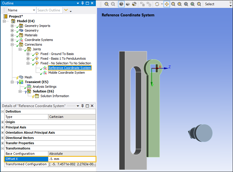
Note: Transformations enable you to manipulate the coordinate systems by entering offsets or rotations in each of the three axes.
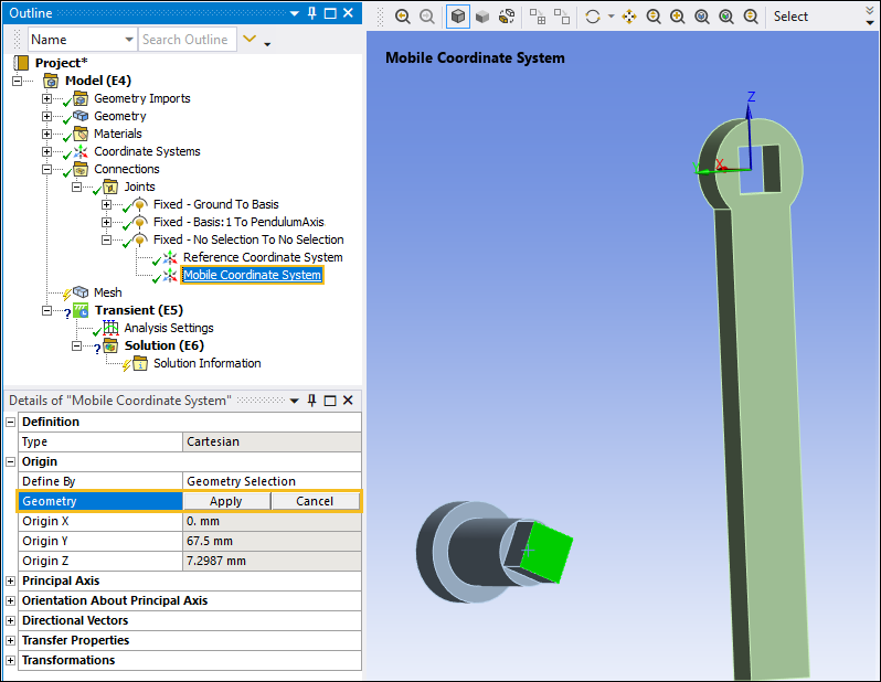
Next, select the Mobile Coordinate System object. This coordinate system is associated with the Arm. Select the field of the Geometry property, select the flat surface on the PendulumAxis as shown, and then click .
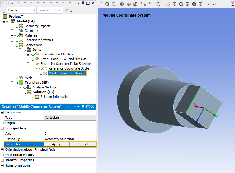
Now, orient the PendulumAxis so that its faces are aligned with the faces on the Arm during the Assemble process.
Select the Mobile Coordinate System object. Under the Principal Axis category, select the field of the Geometry property, select an edge of the PendulumAxis, and the select .
The three bodies have been oriented and aligned and are ready to be assembled.
In the Outline, select the Connections object.
From the Connections Context tab, select from the Joints group.
The parts should snap together in place as illustrated below. If the geometry you're attempting to assemble has not snapped into place as expected, you should retrace your previous steps to make sure that the coordinate systems are properly oriented. If your assembly has been successfully performed, then click Set on the context tab to place the assembly in its assembled position to start the analysis.