


A Hydrodynamic Structure object is automatically added to the Static Structural analysis when you create a Hydrodynamic Pressure object.
Clicking the ![]() icon
creates an additional Hydrodynamic Structure object, and you can repeat this up to the number of
structures in the hydrodynamic model.
icon
creates an additional Hydrodynamic Structure object, and you can repeat this up to the number of
structures in the hydrodynamic model.
Alternatively, you can right-click the Static Structural analysis and select > from the context menu.
The Details of Hydrodynamic Structure panel provides options that allow you to configure the Hydrodynamic Structure object. These are described below.
The Activity field allows you to set the suppression state of the Hydrodynamic Structure object. Set to Suppressed if you want to exclude the structure from the mapping.
When your time domain Hydrodynamic Response analysis contains more than one structure, you must select the name of the structure (in the Hydrodynamic Response system) that you intend to map loads from using the Name in HR Analysis option.
The fixity of the selected structure in the Hydrodynamic Diffraction analysis is indicated by Structure Fixity. When this field shows Structure is Fixed in Place, the radiated wave pressure component will be zero and no structure accelerations will be calculated. In this case, for consistency, the structure should also be fixed in the Static Structural analysis (for example, by a Fixed Support). If the Structure is Free to Move you are recommended to use the Weak Springs option (in the Static Structural Analysis Settings) to mitigate rigid body motions.
If the selected structure has Internal Tanks associated with it in the Hydrodynamic Response analysis, the number of tanks is shown in the read-only Number of Internal Tanks field.
If the selected structure has Cables, Tethers or Joints attached to it in the Hydrodynamic Response analysis, the numbers of these features are shown in the read-only Number of Cables/Tethers/Joints on Structure fields.
If the selected structure has Morison Disc elements associated with it in the Hydrodynamic Response analysis, the number of discs is shown in the read-only Number of Morison Discs on Structure field.
When Model Type for Mapping includes External Surfaces, use the External Surfaces options to select the surfaces that you want to map hydrodynamic pressures onto. Surfaces can be selected either by Named Selection, or by Geometry Selection from the graphical window.
When Model Type for Mapping includes Line Bodies, use the Line Bodies options to select the beams that you want to map hydrodynamic loads onto. Line Bodies can be selected either by Named Selection, or by Geometry Selection from the graphical window.
When the Perform Mass/Inertia Check option is set to ‘Yes, Selected Bodies Only’ or ‘No, Use Hydrodynamic Model CoG Position’, you must select the bodies in the structural model on to which the hydrodynamic rotational velocities and accelerations should be applied. Where relevant, these bodies will also be used in the comparison of mass properties between the hydrodynamic and structural models. Bodies can be selected either by Named Selection, or by Geometry Selection from the graphical window.
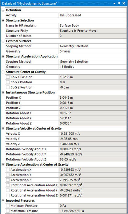
The Minimum and Maximum Pressures on diffracting panel elements are reported.
When Model Type for Mapping includes Internal Tanks, the Minimum and Maximum Internal Tank Pressures are provided. When Model Type includes Line Bodies, the Minimum and Maximum Beam Loads (as Force per unit Length) are also shown. These quantities are evaluated over this hydrodynamic structure only. For all cases, the position of the structure's center of gravity (in the Static Structural axis system), the translational and rotational velocities, and the resultant translational and rotational accelerations about that center of gravity, are displayed. Where applicable, values are displayed for the time step selected in Display for Time Step.