This section describes problems you may encounter when performing simulations in Motion, as well as actions you can take to resolve the problems.
Motion solver adapts the step size according to the system response. When the acceleration of the system is very large or a high-frequency response occurs, the solver reduces the step size to obtain an accurate solution.
The step size will be reduced if any of the following cases apply:
When a large initial contact penetration causes a contact force that produces a very large acceleration of the system, or a large force is applied for a short time
If the mass and mass moment of inertia of the body are very small or zero
When the stiffness coefficient of a bushing, spring, or contact is relatively large compared to the mass of the body
Frequent change of contact points
Super-fast rotation
Use of very small maximum stiction deformation values in contact parameters
Divergence of control logic
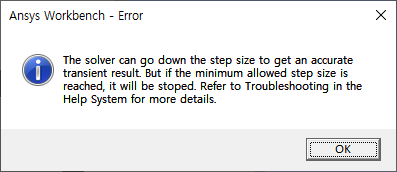
When the current step size of the solver is smaller than the set minimum step size, the following message is displayed and the simulation ends:
To avoid this error, use the Motion Standalone Postprocessor to check the following possibilities, and modify the related entities. If the step size reaches the minimum step size for a very short moment and the results are not reported properly, increase the number of report frames and re-simulate to analyze the results.
Use the acceleration plot and contour to check if a large acceleration occurs at the moment when the step size decreases. In this case, check and correct the entities connected to the body where the abnormal acceleration occurred.
Check if a very large joint reaction force, force entity force, or contact force has occurred. In this case, check and correct the entities that are connected to the body where the abnormal force occurred.
If the step size decreases immediately after the start of the simulation, Use the contact penetration plot to check if there is an initial contact penetration. In this case, move the position of the contacting body so that initial contact penetration does not occur, or set the contact force to increase gradually by using the Increment Time option.
Use the contact force vector display to check if contact points change frequently. In this case, increase the number of contact points by using a finer mesh or by tuning the contact parameters.
A Contact Patch on a Rigid Body must not span multiple surfaces (as shown in the middle image below).
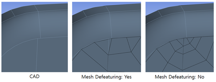
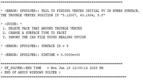
This situation typically causes a solver error similar to that shown below.
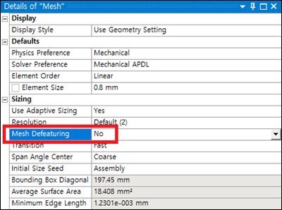
The issue is caused by the Mesh Defeaturing mesh option, which is intended to be used when meshing Flexible Bodies to prevent very small edges or surfaces from ruining the overall mesh geometry. This should not, however, be the case for Rigid Bodies and if a small edge or face is ignored, it can cause a mismatch between the NURBS and the patch on the contact surface. Changing the Mesh Defeaturing option to (see below) will ensure that a single Contact Patch will be contained within a single surface (as shown in the right-hand figure above).