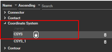
The properties of a coordinate system can be activated by selecting the title of the target coordinate system in the Object Navigator as shown in the figure below.
The Coordinate System properties window is divided into four main sections: Appearance, General, Transformation, and Type. These sections allow you to modify various coordinate system options, such as position, orientation, and parent body, as illustrated in the figure and table below.
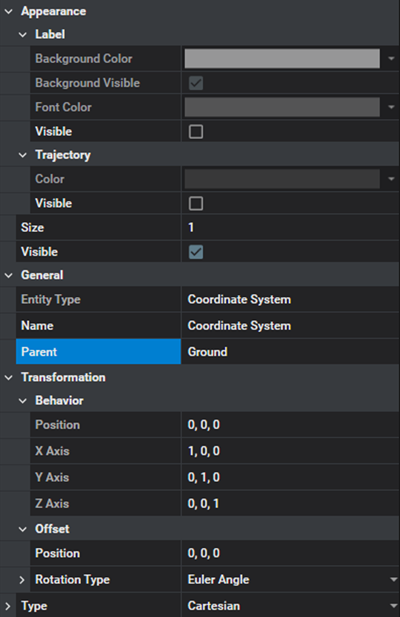
Figure 3.91: Coordinate System Property Details
| Category | Content | Description |
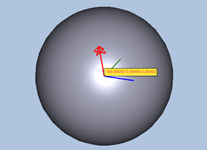
| Appearance / Label | Visible |
Used to show the position vector in the animation view as shown in the figure below.
|
| Background Visibility | Used to set the background visibility of the label. | |
| Backgroud Color | Used to set the background color of the label. | |
| Font Color | Used to set the font color of the label. | |
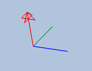
| Appearance / Trajectory | Visible | Used to show the trajectory of the coordinate system. |
| Color | Used to set the color of the trajectory. | |
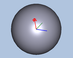
| Appearance | Visible |
Used to show the graphics of coordinate system as shown in the figure below.
|
| Size | Used to set the size of graphics for the coordinate system | |
| General | Entity Type | Used to show the type of entity. |
| Name | Used to define the name of the coordinate system. | |
| Parent | Used to define the parent body or node. The coordinate system is fixed on the parent, and its position and orientation are changed relative to the parent. | |
| Transformation / Behavior | Position | Used to show the position of the coordinate system at the displayed frame. The position can be determined on the screen by using the point picker and the Offset. The picker supports rigid body, node on surface, and marker. |
| X Axis | Used to define or show the orientation matrix of the coordinate system at the displayed frame. The position can be determined on the screen by using the point picker and the Offset. The picker supports rigid body, node on surface, and marker. | |
| Y Axis | ||
| Z Axis | ||
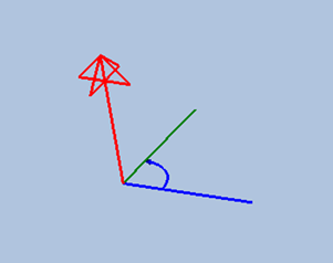
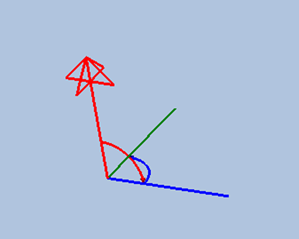
| Transformation / Offset | Angle | Used to apply the rotational offset angles to the orientation of the coordinate system. The input values update the orientation in the Behavior category. |
| Rotation Axis | Used to define the order of rotation axes for the input values. | |
| Rotation Type | Used to define orientation representation for the input values as either of the following types:
For more detailed information, see ????. | |
| Position | Used to apply the translational offset values to the position of the coordinate system. The input values update the Position in the Behavior category. | |
| Type | Type |
Used to define the type of coordinate system. , , or types are available, as shown below.
See Types of Coordinate System for more information. |
| Axix R | Used to define the radial direction for the cylindrical coordinate system. See Types of Coordinate System for more information. | |
| Axis Z | Used to define the height direction for the cylindrical coordinate system.See Types of Coordinate System for more information. | |
| Axis ρ | Used to define the radial direction for the spherical coordinate system. See Types of Coordinate System for more information. | |
| Axis φ | Used to define the azimuth angle direction for the spherical coordinate system. See Types of Coordinate System for more information. |