Next, you will create a Path To Segment Contact object. This creates internal contact between the faces of the path (sprockets) and segments:
Select the Model element in the Project tree.
From the Motion ribbon, click and select .
In the Details panel for the new Path To Segment Contact object, click in the Links Assembler field and select the
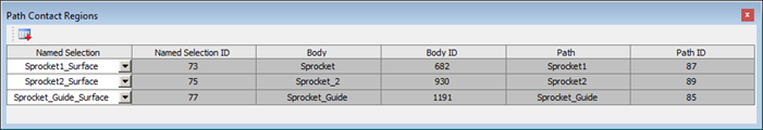
Links
                        Assembler
that you created above.Click in the Path Contact Regions field (where it says Tabular Data).
In the Path Contact Regions dialog, add three new entries and select the Named Selections titled
Sprocket1_Surface,Sprocket2_SurfaceandSprocket_Guide_Surface.In the Details panel, click .
You can check that the geometry information is loaded correctly by clicking again in the Paths field (see below).
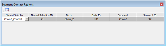
In the Details panel, click in the Segment Contact Regions field (where it says Tabular Data).
In the Segment Contact Regions dialog, add a new entry and select the Named Selection titled
Chain2_Contact.Note: The
Chain1_Contactsurface is not actually in contact with sprocket surface.In the Details panel, click .
You can check that the geometry information is loaded correctly by clicking again in the Paths field (see below).