


The Motion Elastohydrodynamic (EHD) Bearing object supports co-simulation with the Tribo-X solver for lubricated components.
To use this feature you must define a general joint for the journal bearing based on the surfaces of the journal as well as the shaft to which the journal bearing is attached. Additionally, you must restrict the degrees of freedom of the moving body (the shaft) to only the rotational degree of freedom around the rotational axis (z-direction), the translational degrees of freedom in the normal direction (x and y-directions) and, if required, in the direction of the rotational axis (z-direction).
This general joint must then be selected for the EHD Bearing under Scope and Joint.
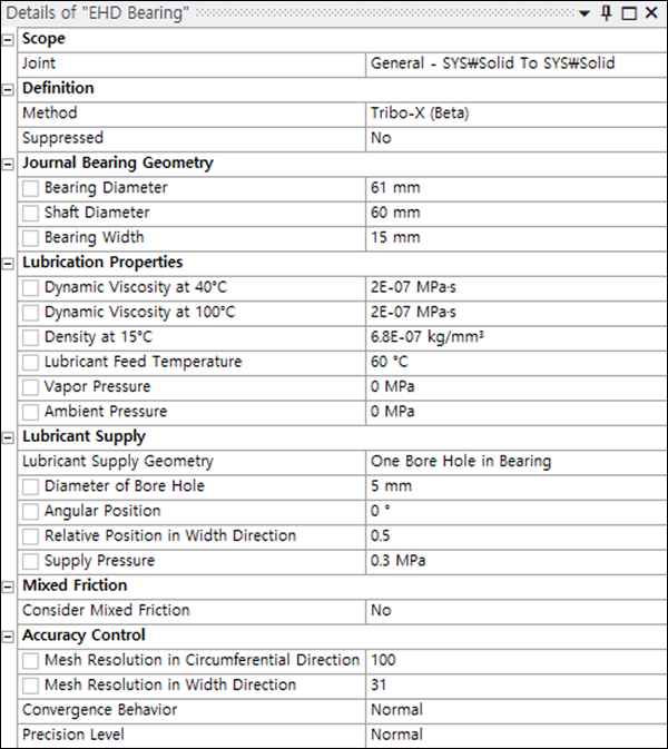
When is selected as the Method, parameters are exposed as shown in the figure below. These are described in the sections that follow.
Lubrication Properties
The properties of the lubricant must be defined with respect to temperature as follows:
- Dynamic Viscosity at 40 °C
The dynamic viscosity (
[pressure]*[time]) of the lubricant at 40 °C. This, and the parameter below, can be derived from the lubricant manufacturer's data sheets.- Dynamic Viscosity at 100 °C
The dynamic viscosity of the lubricant at 100 °C.
- Density at 15 °C
The density of the lubricant at 15 °C. This allows the effective density to be determined based on the defined feed temperature.
- Lubricant Feed Temperature
The temperature of the injected lubricant.
- Vapor Pressure
This defines a critical pressure value. If the pressure falls below this value, formation of gas in the gap will occur.
- Ambient Pressure
This is the pressure value that is assumed at the bearing sides, except when the Lubricant Supply Geometry option is set to (see below).
Lubricant Supply
The lubricant supply for the journal bearing is defined based on the following parameters:
- Lubricant Supply Geometry
The lubricant can be supplied based on one of the following categories:
- Supply Geometry Parameters
Depending on the selected Lubricant Supply Geometry, you must then specify a combination of dimensional parameters as described below:
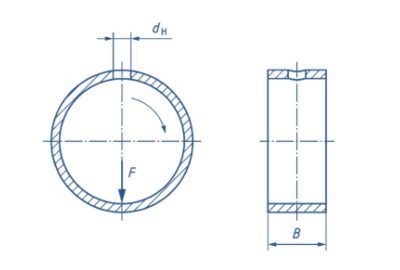
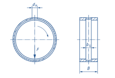
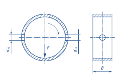
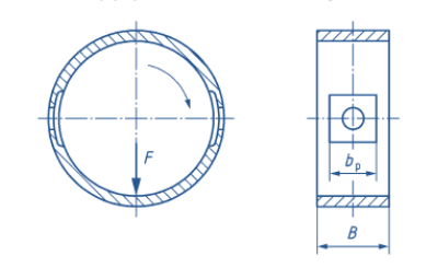
Diameter of Bore Hole - the diameter of the bore hole used to supply lubricant.
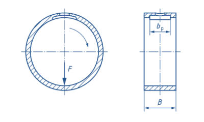
Length of Supply Pocket - the length of the lubricant supply pocket, defined by the arc length of the pocket edge in the circumferential direction.
Width of Supply Pocket - the width of the lubricant supply pocket, based on a rectangular pocket geometry in combination with the parameter below.
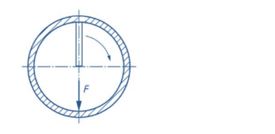
Angular Position - the angular position of the bore hole, where 0° coincides with the x-axis of the general joint on which the EHD Bearing object relies.
Relative Position in Width Direction - positions the supply geometry as a whole along the bearing width. A value of 0.5 positions the supply geometry in the middle of the bearing width. A value of 0.0 positions the supply geometry at the edge located in the negative z-direction, a value of 1.0 at the edge located in the positive z-direction.
- Supply Pressure
The pressure under which the lubricant is supplied to the bearing.
Mixed Friction Definition
Mixed friction conditions can be considered for the journal bearing calculation if required.
- Consider Mixed Friction
Set this option to to consider mixed friction and expose the parameters listed below. When the option is set to , pure hydrodynamic operation of the journal bearing is assumed and no solid contact of shaft and journal bearing is considered.
- RMS Roughness of Bearing Surface
(see below)
- RMS Roughness of Shaft Surface
The topography of the rough surface is described based on the RMS roughness values of the shaft and bearing surfaces as defined by these two parameters.
- Roughness Orientation
This orientation depends on the material and manufacturing process. It can be selected to be predominantly oriented in the circumferential direction (), isotropically oriented without preferred direction of roughness structure () or predominately oriented in axial direction ().
- Plastic Flow Pressure
This is a measure of the surface hardness and must be defined for the material of the shaft or the journal bearing, depending on the surface hardness. The value must be specified for the material with the lower surface hardness, which in most cases is the journal bearing.
- Boundary Friction Coefficient
This value is needed to evaluate the friction in the case of rough contact between journal bearing and shaft. The boundary friction coefficient depends on the shaft and journal bearing material as well as the lubricant.
Accuracy Control
- Mesh Resolution in Circumferential Direction
(see below)
- Mesh Resolution in Width Direction
These two parameters control the number of elements in the respective directions for the solution of the Reynolds differential equation. Higher resolutions increase the accuracy of the calculation results but simultaneously increase the calculation time.
- Convergence Behavior
This can be set to , or to control relaxation factors for the solution of the underlying equations. The setting provides faster calculations but can lead to a worsened convergence behavior. The setting results in higher calculation times but improved convergence behavior.
- Precision level
This can be set to , or to control the maximum deviations of the result quantities when solving the underlying equations. The setting defines higher values for the maximum deviations and correlates with less exact results and lower calculation times. The setting defines lower values for the maximum deviations and correlates with more exact results but longer calculation times.