


You can define various cable-specific parameters in the properties of a line body set to the Cable model type.
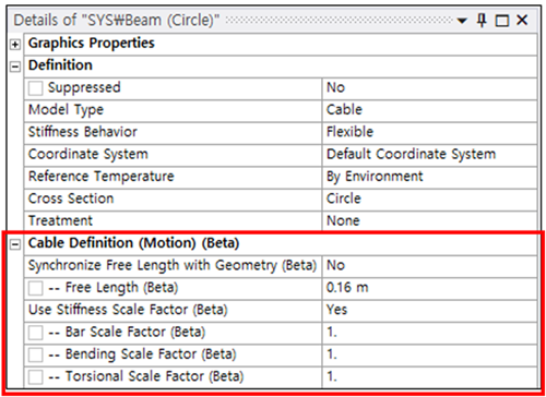
Synchronize Free Length with Geometry
When Synchronize Free Length with Geometry is set to , the free length of the cable is automatically calculated from the geometry, assuming no axial tension or compression. If set to , users can manually define the free length.
- Free Length
This is the cable's length in its undeformed state. The initial value is calculated based on the line body's length from the CAD model. If the free length is set longer than the line body's actual length, tension forces will occur. If set shorter, compression forces will arise.
Use Stiffness Scale Factor
The Stiffness Scale Factor is used to adjust the axial, bending, and torsional stiffness of the cable elements. When set to , the stiffness of the cable elements is modified by multiplying each entry of the beam stiffness matrix by a user-defined scale factor. When set to , all scale factors are set to their default value of 1.
- Bar Scale Factor
Scales the axial stiffness of the beam. This factor is applied to the axial stiffness terms in the beam stiffness matrix.
- Bending Scale Factor
Scales the bending stiffness of the beam. This factor is applied to the bending stiffness terms in the beam stiffness matrix.
- Torsional Scale Factor
Scales the torsional stiffness of the beam. This factor is applied to the torsional stiffness terms in the beam stiffness matrix.