


You will use the option to apply fiber directions from curves so start by creating a few curves.
Click Curve in the main right toolbar.
Click BSpline Curve.
Select Method: From Mesh.
Deselect the Piecewise check box.
Click some nodes around the "hole" from top to bottom (see Figure 8).
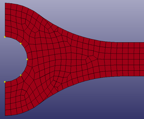
Click .
Create a curve on the upper edge in the same way from left to right (see figure 9).
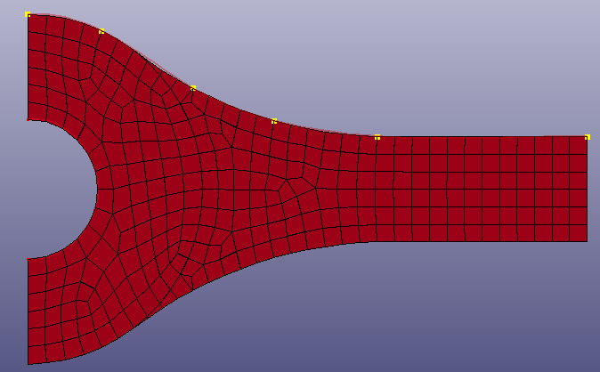
Create a curve on the lower edge in the same way from left to right.
Go back to Element Tools > Element Editing > Composite.
Click the radio button.
Click .
We will map the directions using the Curves option.
Click the Pick option and select the curve in the circular "hole".
Click the button in the Map > Curves box. This creates a discrete vector field which will be used for setting the fiber direction for the circular area.
Create the second vector field from the two remaining curves.
Click the Pick check box.
Select the two curves at the top and at the bottom edges.
Click .
Map the directions for the circular area by using vector map 1.
Select the elements with composite material for the circular area by going to the radio button and use the Select elements option for ply 2 and select the composite material.
Go back to the Direction > Map panel.
Select ply 2.
Select vector map 1.
Click .
The directions for the elements in the circular area is now set.
Map the directions for ply 1 and ply 3 using vector map 2:
Multi-select ply 1 and ply 3.
Select vector map 2.
Select all element by clicking Whole in general selection.
Click .
The direction from the closest vector is used when the direction for each element is set. The directions can optionally be smoothed out so that no abrupt changes occur between two neighbouring elements (as it now is at the symmetry line for ply 1 and 3. You will smooth the orientations in this area by using the Smooth function.
Click the Smooth radio button.
Select ply 1 and ply 3 in the list of plies.
Select all elements (if they are not already selected).
Click and watch the direction to be smoothed out near the symmetry line.
Click .