


Springback is a crucial aspect of sheet metal forming, especially when working with lightweight and high-strength materials. Springback compensation is a widely accepted practice in the stamping industry. Virtual springback prediction and compensation during forming simulation can reduce die-recut costs significantly.
The traditional way to compensate for springback is to refine tooling in several iterations. In each iteration the user analyzes the resulting part, checking it against the design, then modifying the tooling and re-solving. These iterations are repeated until the desired part is achieved.
The Springback Compensation feature enables you to run multiple iterations of the simulation and use the results of each iteration to modify selected tooling automatically, to create final parts that are within defined tolerances of your design.
This feature automates the process, enabling you to determine optimal tooling without tedious manual changes.
To use the Springback Compensation feature:
Define and perform a normal forming simulation that includes one Drawing operation. This feature can only compensate one draw die.
After the simulation, return to the Process tab and choose from the Advance tab of the Process task panel.
Open the Advance tab and click .
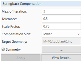
Set the maximum number of iterations.
Set inner and outer tolerances for the geometry and curves that will be corrected (default 0.5 mm).
Set a scaling factor.
Choose the master side of the part geometry where compensation should occur.
Choose a target geometry.
If you require symmetrical compensation, check the box next to Symmetry, then click the button to open the Symmetry Setting task panel.
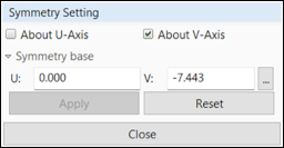
Check the box next to About U-Axis if you require symmetry about the U axis in the local coordinate system.
Check the box next to About V-Axis if you require symmetry about the V axis.
Enter a symmetry base value for each axis you have selected.
Click .
Click to return to the task panel.
Click .
On the Advance tab, click to run the correction process.
The simulation will run until tolerances are met or max. iterations is reached.
After processing, view the results.
A summary details the correction process.
View the percentage of nodes within tolerance, the deviation map, and the deviation vectors for each node.
Each iteration's meshes can be viewed and compared with the target.
You can export the final shapes of the die geometry and trim curves to a CAD file.
In the task panel, click .
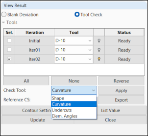
Use this task panel to select an iteration and tool to check the geometry for shape, curvature, undercuts, and element angles.
If the modified tool geometry passes checks, click to save the modified tool geometry to a file.