


The stoning function enables you to perform a virtual stoning of the part to identify surface defects present in the workpiece. Choose from the Analysis Ribbon Elements to display the Stoning task panel and view a digram in the Graphics Window that displays the depth of detected surface defects.
The following options can be applied to the display by checking or clearing the check box next to the option:
- Smooth Results
When checked, the plot contours are smoothed. Clear this check box to view the plot without smoothing.
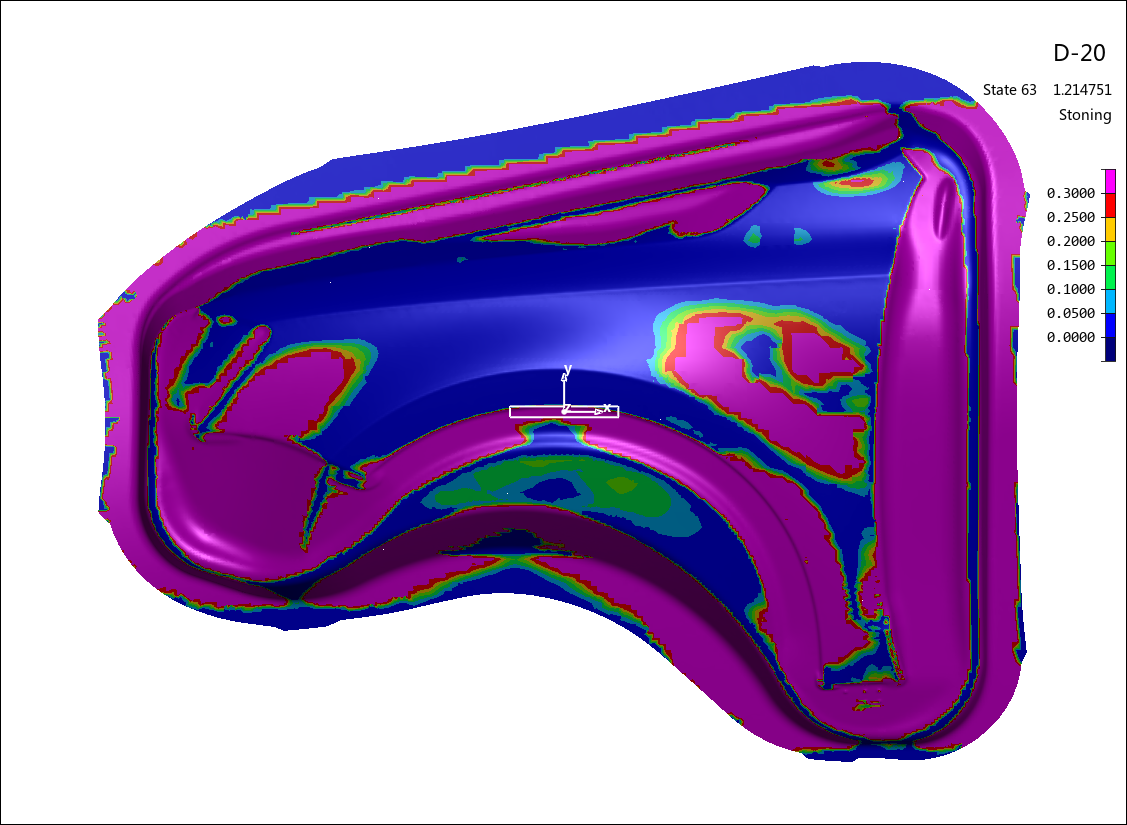
- Show Stone
When checked, a rectangle is displayed on the plot that represents the size and orientation of the stone. Clear this check box to view the plot without this rectangle.
Choose a to orient the stone. If Stone CS is set to , you may choose to orient the length of the stone along the X axis, Y axis, or both X and Y axes. If Stone CS is set to , you may choose to orient the length of the stone along the U axis, V axis, or both U and V axes.
Enter a , press Enter, and click to change the size of the simulated stone.
Choose from the drop-down menu to use the Create stone CS task panel to define a coordinate system for the stone, or choose to use the same coordinate system for the stone that applies to the rest of the model.
Choose or from the drop-down menu to simulate scanning the stone along the upper or lower (as defined by the Z or W component of the you have chosen) surface of the workpiece.
Click to use the List Value Task Panel to pick points to display the depth of the surface defect at those points on the diagram.
Click to use the Contour Setting Task Panel to modify the settings of the stoning diagram contours. Generally, the actual surface defect is very small, so the contour range between Min and Max should be set to small values.
When you are finished with the stoning diagram, click the button to return to Viewing Basic Deformation Results.