


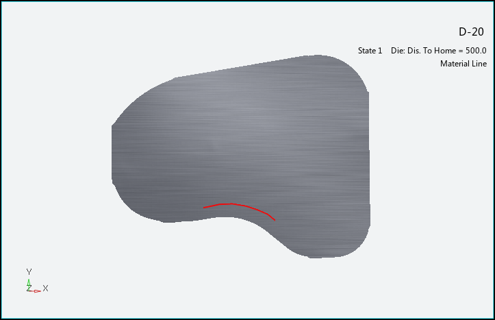
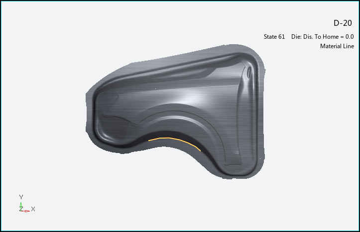
Material lines are often printed on blanks before processing, to be used as references during the forming process. Use the material line function to display the movement of the material from a reference state to the final state of the process. This is useful for looking backward to determine where a particular location on the final part "comes from" on the blank, or looking forward to determine where a particular location on the blank "ends up" on the final part. Choose from the Analysis Ribbon Elements to display the Material Line task panel and generate a material line diagram.
Use the Material Line task panel to select individual operations to view, or to play an animation of the forming process. You must have more than one operation selected to view the animation.
The panel enables you to select a Mapping Method. Select By Nearest to map the material line to the nearest points on the blank. Select By Project and choose a local coordinate system to define how the line is mapped to the blank.
To create a material line diagram:
Click to open the Material Line Task Panel.
Jump to the last frame of interest (usually the last frame of the simulation).
Choose from the Additional Tools
 to open the Create
Lines task panel.
to open the Create
Lines task panel.Draw a line on the geometry by clicking in the graphics window, or by entering numerical node IDs or point locations and clicking after each.
If the line is a closed curve, click to connect the last point to the first, or if the line is an open curve, click after the last point.
When you are finished drawing lines, click to return to the Material Line task panel.
Jump to the first frame of interest (usually the first frame of the simulation).
In the Operation section, click to use the Pick Line task panel to select the line you just drew, then click to return to the Material Line task panel. If you cannot see the lines to pick them,
Click the button (
 ) or step through the
frames of the animation to view material travel as visible with the material
lines.
) or step through the
frames of the animation to view material travel as visible with the material
lines.
Click to write the selected material lines to an IGES file. You can import these lines into other sessions or projects using the Import tool on the ribbon so that you do not have to draw them again.
When you are finished with the material line plot, click the button to return to Viewing Basic Deformation Results.