You may have multiple trimming operations displayed in the Operations tab. Follow the steps below for each one.
Click the trimming operation button (for example, T-20) in the Operations tab to open the trimming operation task panel.
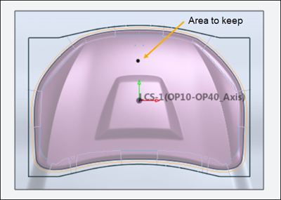
Pick the area to keep after the trimming operation is finished.
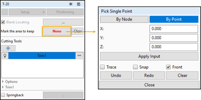
Pick a point on the area inside the trimming curves. You can pick two seed points or nodes to keep two parts after the trim. For example, if you are creating two symmetrical parts, you can pick one point or node within each trim curve to keep both parts.
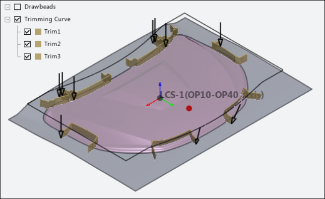
Make sure the trimming curves needed for the T-20 operation are selected in the Feature Tree.
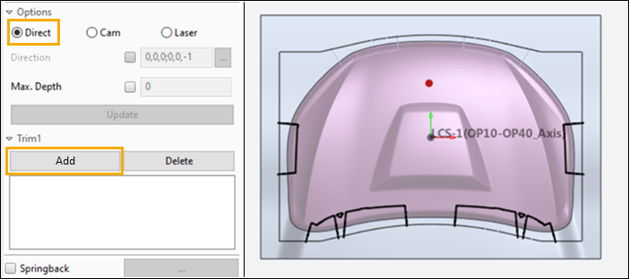
Click Direct, Cam, or Laser to specify the type of cut:
Direct - The cut is parallel to the working direction (the press line).
Cam - The cut is in a specified direction.
Laser - The cutting direction is determined by the normal direction of elements close to the cutting curve.
Sometimes, you only want the trimming curve to cut part of the way through the material. Select the Max. Depth option to only trim the surface that is closer to the trimming curve. Check the check box and set a numerical depth. This will prevent trimming of the opposite side. The depth is consistent with the current Units.
When you have chosen the options for a cut, click to add the trim curve to the list. The figure below shows selected cutting curves for the Trim1 cut in the example.
Define additional cuts, as needed, by clicking the  button on the trimming task panel. In
this example, Trim2 and Trim3 are defined
using the Cam option and specified directions. This yields the
final trimming configuration shown below:
button on the trimming task panel. In
this example, Trim2 and Trim3 are defined
using the Cam option and specified directions. This yields the
final trimming configuration shown below: