


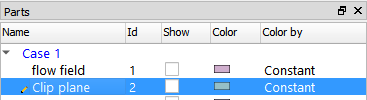
Select the parent. part.
Click the Vector Arrows icon.

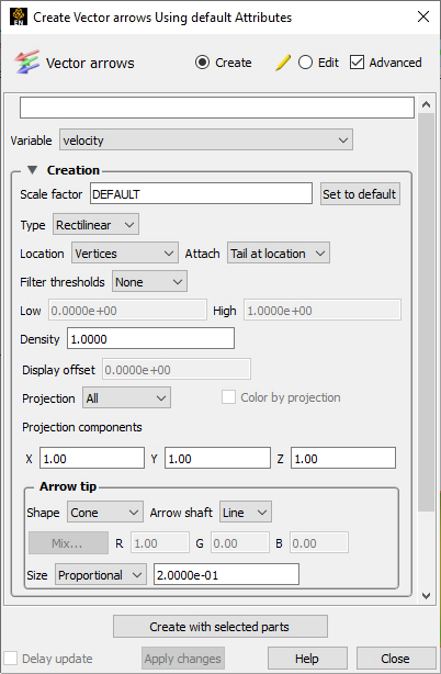
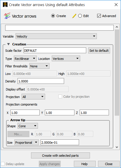
Select the vector Variable to use.
Leave it Default to load a suitable Scale Factor and change it later as desired.
Click .
Select the desired Density (0.0 to 1.0).
The density of the arrows will vary from no arrows (0.0) to arrows at every location (1.0). At intermediate densities the arrows are placed randomly with no user control of their locations.
More options are available by clicking on the toggle.
To quickly create vector arrows on a part, right-click in the part list or in the graphics area and choose Vector Arrows.
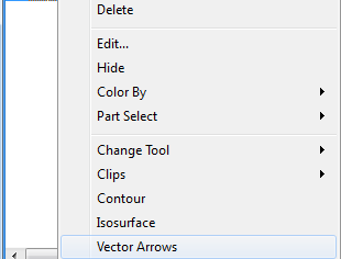
User will be presented with a list of vector variables and then vector arrows will be instantly created on the part using all the defaults.
If only one vector variable is in the dataset, then vector arrows will be created using that variable on the selected part.
Vector arrows are then colored by the vector.
Other vector arrow control the type of arrow, the location of the arrow origin, and arrow filtering options.
To change vector arrow at any time, simply double-click the desired vector arrow part in the Parts list.
Click the toggle.
Select the desired type from the Type pulldown.
Choices are:
Rectilinear
Standard vector arrows: shaft points in local vector direction with length equal to vector magnitude scaled by Scale Factor Value.
Rect. Fixed
Same as Rectilinear except that length is set by Scale Factor value independent of vector magnitude.
Curved
Arrow shaft is the path of a particle trace in the local flow field. Scale Factor becomes “Time” and controls the duration (stopping criteria) for each trace.
Important: This can take a great deal of time for large numbers of vector arrows and/or long Time values.
Select the desired arrow Location of the origin.
Choices are:
Node
Arrows originate from each node of the parent part(s).
Vertices
Arrows originate only from those nodes that are also vertices of the parent part(s).
Element Center
Arrows originate from the geometric center of all elements of the parent part(s).
Select how the vector arrow tail is attached to the Location. This option is not available if the Type is set to . The choices are:
The tail of the arrow is located at the Location specified.
The tip of the arrow is located at the Location specified.
Select the desired filter type from the Filter thresholds pulldown.
Choices are:
None
No filtering – all vector arrows appear.
Low
Display only those arrows with magnitude above the value in the Low text field.
Band
Display only those arrows with magnitude below Low and above High (opposite of Low/High).
High
Display only those arrows with magnitude below the value in the High text field.
Low/High
Display only those arrows with magnitude between Low and High (opposite of Band).
Select the desired tip shape from the Shape pulldown.
None
No tip (default).

Cone
Solid cone shape. When selected, the shaft type may also be chosen
Line - draw the arrow shaft as a line
Solid - draw the arrow shaft as a cylinder
Normal
Single wedge. Good for 2D problems. Plane of the wedge is based on the relative magnitudes of the components.

Triangles
Two intersecting triangles. Good for 2D/3D problems.

Tipped
End of the shaft colored in a different color. Good where other shapes yield too much visual clutter.

Display offset sets the desired display offset.
Note: This is rarely necessary because by default, Display offset is set automatically using the graphics hardware. The display offset moves the vector arrows a short distance away from the surface on which they are defined (typically for hardcopy or animation purposes) in the direction of the surface normal. This is used when a tangential projection is used and the arrows are coincident with the parent part’s surface. A negative offset may be appropriate (depending on orientation). You must turn off the hardware display offset in in order to manually set it here. To turn if off, → → .
Select the desired projection component.
Choices are modified by the Projection components field. Scale the X, Y, and/or Z in the Projection components field. Values less than 1 diminish the contribution, more than 1 exaggerate the contribution. Zero means that the component is not considered and confine arrows to the plane perpendicular to this component. If you choose Tangential or Normal, and turn ON the Color by Projection toggle then the part will be colored by the Tangential or Normal.
All
Display arrows in the vector direction.
Tangential
Display component parallel to surface element.
Normal
Display component normal to surface element.