


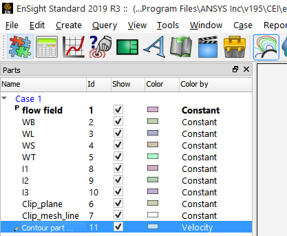
Select the parent part.
Click the Contours icon.

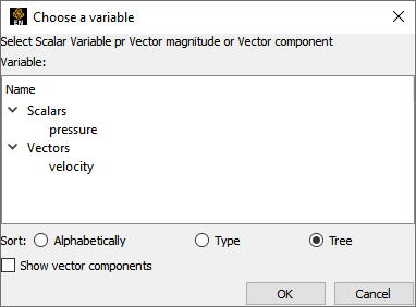
Select the Variable to use.
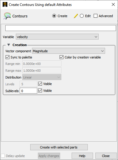
Click the button.
The Contour Feature Panel lets you set the number of contour levels (and sublevels) as well as attach labels to the contour lines. Contour lines can be synced to the palette levels or can be chosen manually.
If You Want Contour Lines for Each Level of the Palette
In the Parts list, double-click the contour part you wish to edit.
Select .
Select the Variable and the component or magnitude if a vector.
Toggle on .
Select the number of sublevels desired (if any). And make sure toggles are set as desired.
See Edit Color Palettes for how to set the color palette levels.
See Edit Color Palettes for how to set the color palette levels.
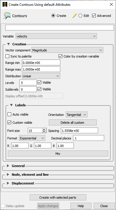
If You Want to Set the Contour Line Ranges
In the Parts list, double-click the contour part you wish to edit.

Select .
Select the Variable and the component or magnitude if a vector.
Toggle off .
Specify the Min and Max Range.
Specify the Distribution for the Range.
Specify the number of Levels and Sublevels.
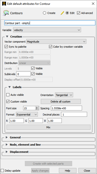
If You Want to Place Labels on the Contour Lines
In the Parts list, double-click the contour part you wish to edit.
Select .
Auto labels will create a label on each main contour loop with a spacing as specified.
Custom labels: Right-clicking
Toggle on or off the visibility of the custom created contour labels.
Custom labels can be created by right clicking on a contour loop and choosing → .
You can also remove any label by right mouse clicking on the label and choosing the → option.
Label formatting
You can control the label orientation, format (linear, log, or quadratic), size, and spacing.
Right click on a part in the Parts list or in the graphics window.
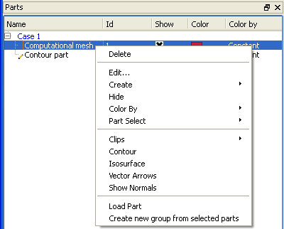
In the resulting pulldown, choose .
A window will pop up to choose a variable.
This then automatically creates a contour part with the default settings using the selected variable and using the right-clicked part as the parent part.