After achieving the equilibrium state for free rolling in a straight line, a cornering analysis develops a slip angle in the tire by increasing the lateral component of the translational velocity of the tire. Slip angle α is the angle between the travel direction of the vehicle and the direction toward which the rolling tire is pointing.
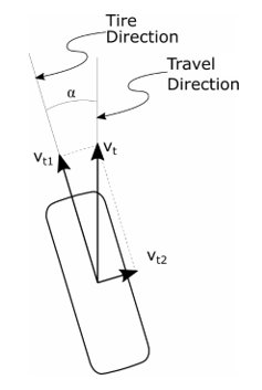
The vehicle’s travel direction is the vector sum of the tire’s forward and lateral velocity components, denoted by Vt1 and Vt2, respectively.
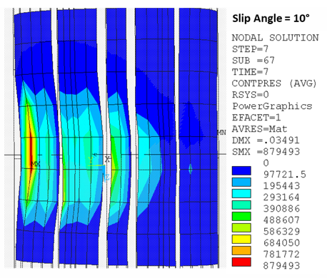
Example 4.11: Cornering Analysis with a 10° Slip Angle
/com *************************************************************
/com Cornering analysis on the 3D model with 10-degree slip angle
/com *************************************************************
time,7
nsubst,50,200000,30
outres,all,all
sstate,define,Etire,spin,FRS,points,0,0,0,0,1,0
!Velocity components: Vy= Vt*sin(10°),Vz= Vt*cos(10°), where Vt= 20m/s
sstate,define,Etire,Translate,,3.473,19.696
sstate,list
rescontrol,,all,last
solve
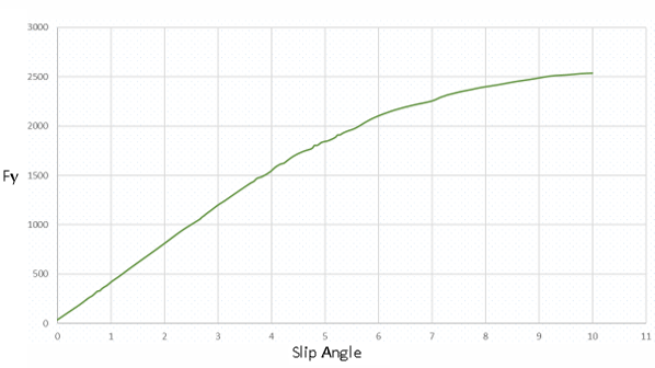
You can also obtain a series of steady-state rolling solutions at various slip angles. The corning force acting on the tire is calculated as a reaction force in the lateral direction on the pilot node of the tire-rim contact pair.