Awareness of the limitation of solid modeling can help you build a better solid model. It is worth spending time thinking about aspects of your model such as mesh sizing, extrusion methods, and geometry operations. For example, it can often be more robust to extrude from the inside out.
This section gives an overview of the limitations of these advanced modeling features:
- Mesh Extrusion
The solid model relies on the extrusion of a shell geometry mesh. As the extrusion directions and operations increase the solid model generation reaches a limit of how heavily a shell mesh can be distorted. If the topology of the structure is complex then the extrusion operations can result in ill-formed elements which are subsequently deleted in the element check.
- Drop-Off Elements
There are transition regions where an edge of a solid model extrusion is reduced to a series of Drop-Off elements. This reduction in thickness will result in a local reduction in stiffness that should not be overlooked.
- Cut-Off Elements
Cut-Off elements are decomposed into homogenous tetrahedral and prism elements. These elements can cause abrupt changes in the structural stiffness which may lead to higher stresses and IRFs. The results in the proximity of Cut-Off elements should be evaluated with care.
- Connect Butt-Jointed Plies
The ability to connect adjacent plies is currently restricted to plies that appear sequentially in the same Modeling Group. Consequently, there a certain arrangement where a ply drop-off cannot be evaded.
- Solid Model Extrusion Offset
The solid model extrusion starts from a reference shell and the lay-up definition. An extrusion with an offset to the reference geometry is not possible.
- Sampling Points, Section Cuts, and Sensors
Sampling points, Section Cuts, and Sensors give information about the lay-up as it was defined in the Modeling Ply Group. The changes as a result of geometric operations in the solid model are not reflected in these features. While Cut-Off plies still appear in the sampling point, these plies show zero stress and strain during postprocessing.
- Recomputation of ISS
The recomputation of interlaminar shear stresses only corrects the stresses of layered elements. Homogenous elements (Drop-Off and Cut-Off elements) retain the interlaminar shear stresses of the .RST file.
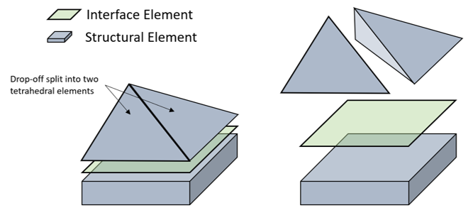
- Interface Layers / Elements
Element faces located above and below an interface element must have the same shape (quadrilateral or tetrahedral). If their shapes are not the same, the interface element is removed. This can happen due to the effect of Drop-Off elements (as shown in the figure below). It can also happen when interface elements intersect a Cut-Off Geomety and the interface element is not updated. As a result, the interface element does not conform to the new shapes of the adjacent top and bottom elements.
Figure 3.37: A quadrilateral interface element surrounded by a brick element and two tetrahedral elements created when the Drop-Off is split