


Lighting System Reference Tables
This section describes the different sections of the Lighting System Excel file.
- Edit the Lighting System Name in the Excel sheet, then save the file (or save as to keep the original file and save the new one).
- Load the Excel Lighting System in Ansys AVxcelerate Lighting and Sensors.
- Save the project.
General Parameters
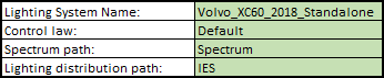
The first section of the Excel file allows you to define the general parameters of the Lighting System.
|
Parameter |
Description |
Remarks |
|---|---|---|
|
Lighting System Name |
Represents the name you give to the Lighting System. |
This is this name displayed in Ansys AVxcelerate Lighting and Sensors (or used by Ansys AVxcelerate Lighting and Sensors to identify duplicates). |
|
Control law |
The Control law (previously programmed) is an identifier allowing you to verify if the lighting system is compatible with the corresponding Ansys AVxcelerate Lighting and Sensors Plug-In sample (C++) or Control law. |
This field refers to a C++ simulated control law defined in the Ansys AVxcelerate Lighting and Sensors Plug-In. |
|
Spectrum path |
Represents the path of the IES or Spectrum folder from where you find the *.ies or *.xmp files. |
Make sure the path is correctly related to the location of your Excel configuration file:
|
|
IES path |
Headlamp Parameters
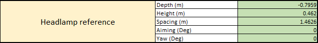
The Headlamp Reference table allows you to define the position and orientation of the whole Lighting System (i.e. both projectors) on the car from the Lighting System referential. For more details see Lighting System Position and Orientation.
|
Parameter |
Description |
|---|---|
|
Depth (m) |
Defines the position of the Lighting System on the longitudinal axis (Z) of the vehicle from the front axle. |
|
Height (m) |
Defines the position of the Lighting System on the vertical axis (Y) of the vehicle from the wheel radius. |
|
Spacing (m) |
Defines the distance between the two projectors, therefore it defines the position of each projector on the lateral axis (X) of the vehicle. |
|
Aiming (deg) |
Defines the elevation of the Lighting System, ie. the rotation around the X axis of the Lighting System referential. |
|
Yaw (deg) |
Defines the lateral angle of the Lighting System, i.e. the rotation around the Y axis of the Lighting System referential. |
Module Parameters
The Module table allows you to add and/or configure modules.

|
Parameter |
Description |
Remarks |
|---|---|---|
|
Module Definition (ID) |
Represents the name of the module ID. Reminder: A module is a set of lamps, each module can rotate independently of the rest of the projector in an adaptive front-lighting system perspective. |
Each Module ID must be unique. |
|
Relative Height Position (m) |
Defines the height of the module with respect to the projector's position when it is defined in the Headlamp Reference, or with respect to the Lighting System referential when the projectors' position is not defined. |
For more information, see Setting Module Position according to the Projectors' Center or the Lighting System Referential. |
|
Relative Lateral Position (m) |
Defines the lateral position of the module with respect to the projector's position when it is defined in the Headlamp Reference, or with respect to the Lighting System referential when the projectors' position is not defined. |
|
|
Relative Depth Position (m) |
Defines the longitudinal position of the module with respect to the projector's position when it is defined in the Headlamp Reference, or with respect to the Lighting System referential when the projectors' position is not defined. |
|
| Relative Aiming (Deg) |
Defines the elevation of the module, ie. the rotation around the X axis of the module. |
|
|
Relative Yaw (Deg) |
Defines the lateral angle of the module i.e. the rotation around the Y axis of the module. |
|
|
Glare Sphere radius (m) |
Defines a sphere radius that generates a sphere representing the glare for the module. |
Decreasing the glare sphere radius increases the glare value for an exterior observer. |
|
Spectrum File |
Defines the name of the *.spectrum file you want to apply to the module. |
A spectrum file is needed only when the Intensity File set for the lamps is a IES or a photometric XMP. No spectrum file is needed if you use a spectral *.xmp, as the spectral information is embedded in XMP. |
Lamps Parameters
|
Parameter |
Description |
Remarks |
|
|---|---|---|---|
|
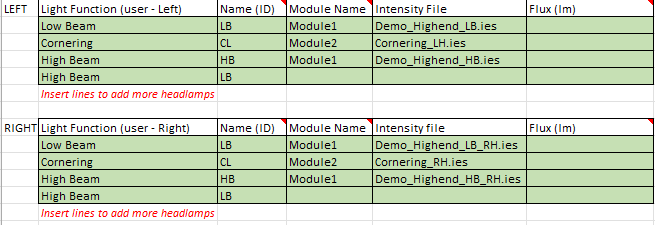
Light Function |
Defines the Light Function of the lamp from the predetermined list:
|
Several lamps may have the same Light Function. One lamp (defined by its ID) may have several Light Functions, however one lamp cannot be included in several modules. |
|
|
Name (ID) |
Defines the name of the lamp. |
Each lamp must have a unique identifier in the scope of each projector. |
|
|
Module Name |
Defines the module (among those present in the Module table) to which belongs the lamp. |
A same lamp cannot be included in several modules. |
|
|
Intensity file |
Defines the name of the *.ies or *.xmp file defining the photometric properties of the lamp. |
Only one *.ies or *.xmp file can be set for one lamp (defined by its ID) per projector. Ansys AVxcelerate Lighting and Sensors does not support Conoscopic *.xmp files. For more details, refer to Creating an XMP File in Speos for a Lamp. |
|
|
Flux (lm) |
Specifies a different flux from the one of the *.ies file configured for the lamp. |
This parameter is optional. | |
Lit Appearance Map Parameters
The Lit appearance map table allows you to define the lit appearance (the visualization of the lamp edges) of the front and rear lamps, which is required for Car Detection with MIL Camera.
The lit appearance map is defined with a radiometric XMP file created with Ansys Speos, loaded in the Excel Template, see Configuring the Lit Appearance for Lamp Edge Detection.
