


Starting from DesignModeler 14.5, you can import geometry from CAD models into DesignModeler in one of two geometry types or representations:
Workbench Geometry: This is a form of geometry representation that is used by various applications within Ansys Workbench, including Workbench Mechanical and Workbench Meshing.
DesignModeler Geometry: This geometry representation is used only by the DesignModeler application. Almost all geometry editing operations are performed in this geometry representation. Geometry in versions of DesignModeler prior to DesignModeler 14.5 are entirely in this form.
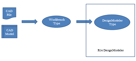
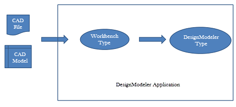
The following diagrams illustrate how geometry information is transferred from the CAD file or session into Workbench applications.
In DesignModeler 14.0 and earlier versions, the CAD geometry is first converted to the Workbench representation and then always converted to the DesignModeler geometry representation before being made available for model editing.
Starting from DesignModeler 14.5, the CAD geometry can be imported as either the Workbench geometry type or the DesignModeler geometry type. When the Workbench format is chosen, the model can still be edited using any of DesignModeler’s features. A conversion from the Workbench geometry type to DesignModeler geometry will be automatically performed when required.
While conversion from Workbench format to DesignModeler format will occur automatically as needed, the extent of the conversion may vary. In some instances, DesignModeler will convert entire bodies into the DesignModeler type while in others, only specific local entities will be converted. For example, if you choose to apply a blend to an edge of a Workbench geometry using the Blend feature, the entire body will be converted automatically to DesignModeler geometry and then the blend operation will be executed on it. If you choose an edge of a line body in Workbench representation and choose to extrude it to create a surface or solid body, then only the selected edges will be internally converted to DesignModeler type with which the extrude operation will be executed.
Instancing information among imported bodies will be lost on conversion from Workbench geometry type to DesignModeler type.
All DesignModeler features will automatically convert the geometry to DesignModeler type before performing the particular feature operation. However, sometimes the conversion step can fail in which case the feature will also fail. This happens for several reasons:
The conversion of a Workbench type body that is disjoint might have produced multiple DesignModeler type bodies;
A failure to convert specific faces of the Workbench body may cause the resultant DesignModeler body to be of a different type, e.g. a surface body instead of solid body;
A non-manifold configuration of the Workbench geometry may fail to construct an equivalent DesignModeler representation, in which case the result may not yield the same body type.
Examples
| Conversion failure due to disjoint bodies: | |
 | 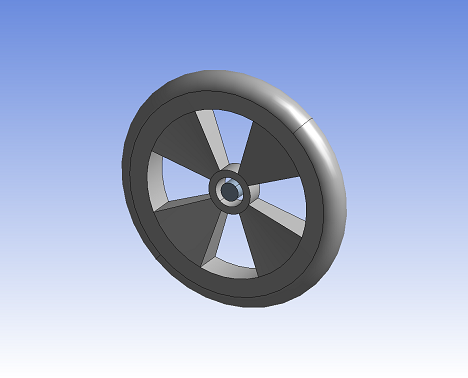 |
Shows part imported from a CAD system as one body of Workbench type. | Shows two bodies when the same body in previous figure is converted to the DesignModeler format. |
The first picture shows a CAD model imported as Workbench geometry. The result is a single body even though the cylindrical geometry at the hub is not connected to the rest of the wheel. When this body is converted to DesignModeler type, the result is two bodies.
| Conversion failure due to incomplete conversion: | |
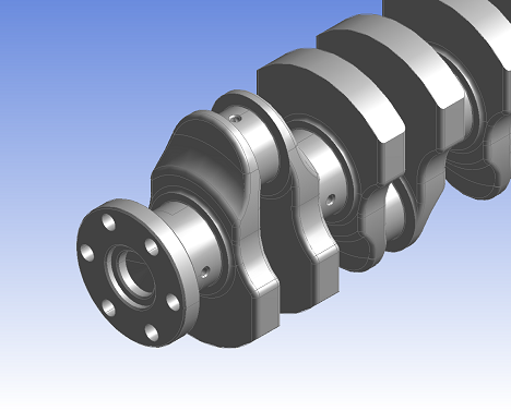 | 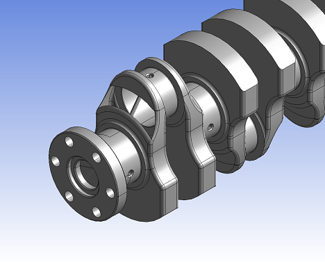 |
Figure shows a CAD model of a crank shaft imported as a Solid body in Workbench Geometry format | Figure shows the same CAD model imported as a Surface body in DesignModeler format. Notice the missing face. |
The first picture shows the CAD model imported as Workbench geometry. When converted to DesignModeler geometry, one of the faces could not be converted and this results in the body being a Surface body in the DesignModeler format.
When a conversion failure occurs, users can apply the Conversion feature to convert the geometry to DesignModeler type and use additional features to further cleanup the converted bodies before proceeding. For more detailed information on the use of this operation, see Conversion feature.
Add Conversion Feature Before Selected Feature: You can use this context menu item to automatically insert a Conversion feature with the failed bodies as its input just before the feature that failed.
Add Conversion Feature After Attach Feature: You can use this context menu item to automatically insert a Conversion feature after the Attach feature that imported the bodies used.
Other Feature Failures — DesignModeler features will automatically convert any required geometry to DesignModeler type before performing the particular feature operation. The feature operation can sometimes fail even when the automatic Conversion succeeds with an error message that entities are not valid. This can occur when the input geometric entities to the feature do not exist in the converted model (DesignModeler Geometry) due to simplify or cleaning or healing methods applied during conversion. In such cases it is recommended to perform conversion using Conversion feature before the particular feature operation.
Importing a CAD model as Workbench geometry will be faster than as DesignModeler geometry, since one less conversion step is required. Bodies will automatically convert to the DesignModeler type as they are undergo operations. Unmodified bodies in the Workbench geometry representation can be passed on to downstream applications without converting to the DesignModeler representation. This workflow can be particularly useful when modifications to only a few bodies in the CAD model are necessary before transferring them to a downstream application for meshing and analysis.
Note: IGES, STEP, MCNP, and Parasolid files are always imported as DesignModeler geometry. All other CAD models and files may be imported in either geometry representation.