


The Vista TF program is a streamline curvature throughflow program for the analysis of any type of turbomachine, but has been developed in the first instance primarily as a tool for radial turbomachinery analysis. The program enables you to rapidly evaluate radial blade rows (pumps, compressors and turbines) at the early stages of the design.
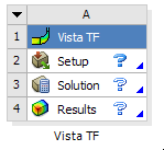
Vista TF is operated from Ansys Workbench by working with either the Vista TF component system or the Throughflow analysis system. The Vista TF component system has three cells: a Setup cell, a Solution cell, and a Results cell:
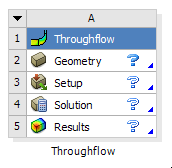
The Throughflow analysis system is essentially a Vista TF system with an added Geometry cell:
The name of the system is changeable upon first adding the system, or by right-clicking the blue cell and selecting Rename, then typing in a new name. Note that the name of the system appears below the system.
To create a new Throughflow analysis system in Workbench, you can drag the Throughflow analysis system from the toolbox to the Project Schematic, or double-click the system in the Toolbox. You can also create a new Throughflow analysis system by right-clicking a Blade Design cell in a Vista CCD, Vista CPD, or Vista RTD component system, and selecting Create New > Throughflow. Upon creating a Throughflow system using data from any one of the Vista CCD, Vista CPD, or Vista RTD systems, each of the cells in the Throughflow system is updated automatically.
Vista TF uses the following input to define a run:
A geometry (*.geo) file
Setup cell properties
Three Vista TF template files
a control data file (*.cont)
an aerodynamic data file (*.aert)
a correlations data file (*.cort)
The general procedure for running a simulation in Vista TF is:
Drag the Vista TF component system from the toolbox to the Project Schematic, or double-click the system in the toolbox.
Specify a geometry file using either one of the following methods:
Connect an upstream Geometry cell that contains a VistaTFExport feature to the Setup cell.
If there is more than one VistaTFExport feature, then the first valid and unsuppressed one is used.
Right-click the Setup cell, select Import Geometry, and browse to select a geometry (*.geo) file.
Double-click the Setup cell, then configure the Setup cell properties.
For details, see Vista TF Setup Cell Properties.
Optionally customize one or more of the three template files (*.cont, *.aert, *.cort).
For details on customizing the template files, see Customizing the Vista TF Template Files.
Update the Solution cell, or update the project, to generate a solution.
Double-click the Solution cell to view the solver output.
Double-click the Results cell to view the results in CFD-Post.
The Results cell has one property that you can edit to control report generation.
When the analysis is complete and the project is finished, you save the project (and therefore the associated files). Once a project has been saved, it can be re-opened at a later date for review or modification of any aspect of the simulation.
Important: Saving a project enables you to re-open the project on the machine that originally created it. To make the project available on another machine, you need to use File > Archive to create a project archive. To open the project on a different machine, run File > Restore Archive on that machine.