


This object may be used to include the viscous drag of the wind on the superstructure of a fixed or floating structure using tabular input in the Wind Force Coefficients window. The term wind force coefficient is used to differentiate these coefficients from traditional drag coefficients and from coefficients of current force.
To add a Wind Force Coefficients object:
Select a Part in the tree view.
Right-click the Part and select , or click the Force Coefficients icon in the Parts toolbar and select Wind Force Coefficients from the dropdown menu.
Select the Wind Force Coefficients object in the tree view and enter the coefficients in the Wind Force Coefficients window that appears below the model. Enter the Direction of the wind (-180 to +180 degrees), the X force coefficient (Translation X), Y force coefficient (Translation Y), Z force coefficient (Translation Z), Rotation about X coefficient (Rotation X), Rotation about Y coefficient (Rotation Y), and Rotation about Z coefficient (Rotation Z). The number of rows is increased as each entry is made, up to a maximum of 41 rows.
The wind force coefficients are defined as the force or moment per unit velocity squared. The moment is about the center of gravity of the structure. These forces are a function of the relative velocity between the structure and the air. This means that the wind coefficient should still be input even when there is no wind present, as the relative velocity is generally non-zero for a dynamic analysis.
The Coefficient Data table must include an entry for the direction of -180 degrees. The coefficients defined for -180 degrees are automatically copied to the +180 degrees row, and these copied values cannot be modified (but will update if the -180 degree values are subsequently modified). Direction entries outside the range of -180 to +180 degrees are automatically adjusted to this range, and rows are sorted in ascending order of Direction. Duplicate Direction entries are not valid and may be removed by selecting the entire row and pressing the Delete key.
Coefficient Data can be entered manually, can be copied and pasted from an external source (for example, an Excel spreadsheet), or can be imported from a comma-separated values (.CSV) file using the Import CSV File option. For the Import CSV File option, the file must meet the following requirements:
Has the .CSV extension.
Contains values separated by commas, tabs, or single spaces (not multiple spaces).
Contains exactly 7 columns, and no more than 41 rows.
The unit system of the data in the .CSV file is assumed to match the display unit system of the project. However, the imported data can be modified by setting the Length Unit for Imported Data, Rotation Unit for Imported Data , and Force Unit for Imported Data to the required unit system.
Note that the forces are in the directions of the axes, not in the direction of the wind. For example, for relative wind velocity V in direction ϕ:
| force in X direction = WIFXϕ.V2 |
| force in Y direction = WIFYϕ.V2 |
| moment about Z axis = WIRZϕ.V2 |
where WIFX, WIFY and WIRZ are the coefficients. Similar equations apply for force in Z and moments about X and Y.
The coefficients are applied in a moving axis system. This means that the axes move with the structure. Since there is no structure local axis system available, the initial coefficient data must be defined relative to the global coordinate system when the structure is in the position as defined in the geometry. For example:
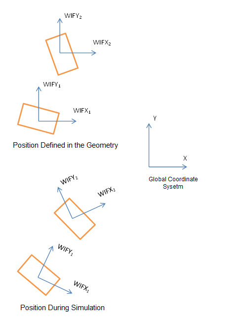
Note:
Only one active Wind Force Coefficient object may be included for each structure.
There is a limit of 41 unique directions for the enabled Wind Force Coefficient and Current Force Coefficient tables combined. Each table may have an entry for the same Direction value.
If a direction is specified for Current Force Coefficients that does not exist for Wind Force Coefficients then linearly interpolated values will be utilized for the Wind Force Coefficients for that direction, based upon adjacent defined directions.