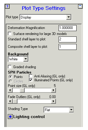
This panel lets you set the following general options :
- Deformation Magnification
View magnified grid deformations. Input the magnification you want to use (1.0 gives no magnification).
- Surface rendering of large 3D models
3D models using hexahedral elements (e.g. Lagrange or Euler) are usually rendered using all the elements. Check this box to render models using only external faces. This makes the process much quicker. This option cannot be used for all plots (e.g. plots with opacity applied).
- Standard shell layer to plot
Set the layer that is plotted for standard shells in material location plots, material status plots, and material contour plots.
- Composite shell layer to plot
Set the layer that is plotted for composite shells in material location plots, material status plots, and material contour plots.
- Background
Set the background color for the view panel.
- Graded Shading
Control the color, including color grading, for the background of the View panel.
You may select a color to be used for each of the four corners of the display by pressing the buttons:

The selected (Default) colors shown here will produce the following background:
- SPH Particles
Controls for the display of SPH particles are only shown when the model contains SPH parts. In this section, the controls for displaying the points with anti-aliasing and illuminated points are accessible. In addition, control of particle display size and amount of fade for outliers can be set.
The figures below compare plots with and without the illuminated points option active:
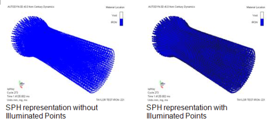
The fade outliers slider gives you the ability to fade in and out of view of the SPH particles, which exist outside of the range that is set in the contour panel when using the truncate facility. This facility is only available when illuminated points are displayed.
Note: Unchecking the Illuminated Points option can help resolve the issue concerning the disappearance of the Ansys logo for models with SPH bodies in Autodyn. Once the Illuminated Points option is unchecked, you may need to click another button in the Navigation bar (for example, Plots) for the logo to reappear.
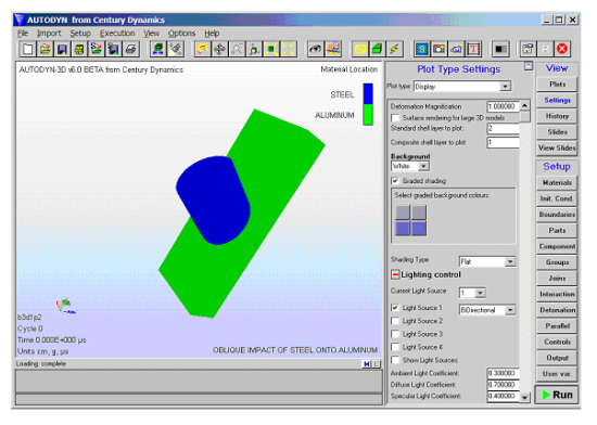
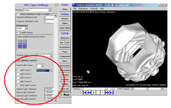
- Advanced Image Shading and Lighting Options
A set of advanced shading and lighting options is available
Using a combination of the above options, metallic looking surfaces can be rendered, for example.
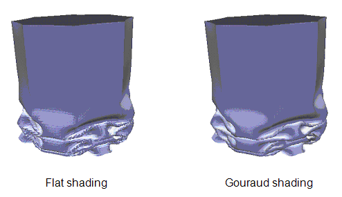
- Shading type
The shading type can now be selected as either flat or Gouraud. For flat shading every point on a face is given the same intensity. For Gouraud shading, the mesh is shaded so as to give the appearance of curved surfaces. The intensity for each point is interpolated from the normal of the face vertices.
- Lighting Control
The advanced lighting control lets you specify up to 4 different light sources and also to control the direction and form of each light source.
The following options are available:
Current light source
Select the current light source to be interactively transformed, after selecting the "Transform Light" button on the toolbar.
Light source toggles
The number of light sources required (up to a maximum of 4).
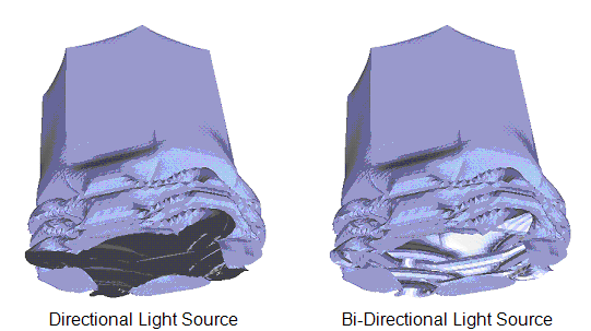
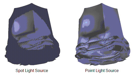
Light source type
Select between directional, bi-directional, spot, or point light sources. Examples of these are shown in the figure below.
Show light sources
The direction and position of the light sources is shown on screen by white arrows (switch the background color to black). Examples are shown in the figure below (from left to right) for bi-directional light source, spot light source, point light source and directional light.
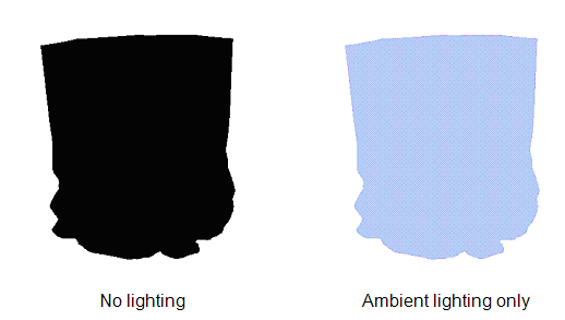
Ambient, Diffusive and Specular Light Coefficients
The ambient light coefficient controls the amount of background lighting. Ambient light is non-directional, affecting all parts of all surfaces equally.
Diffuse light reflectance controls the proportion of the available non-ambient light that the object reflects equally in all directions. Non-ambient light emanates from the directional and point light sources.
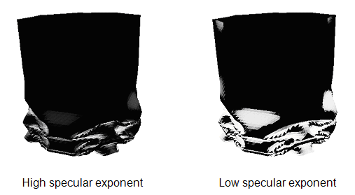
Specular highlights of a particular color and brightness are created when the direction of incoming light (from a directional or point light source) is "sufficiently close" to the viewing direction. The specular reflection coefficient determines the brightness of such highlights.
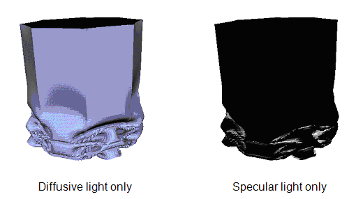
The specular exponent determines what "sufficiently close" means. The greater the sharpness, the smaller (more focused) the size of the specular highlight.