Introduction
The Group option enables you to group an arbitrary (independent of Part and Component) selection of nodes faces or elements on which operations can subsequently be performed.
An interactive method of selecting groups of nodes, faces or elements is available. The selection is made by drawing a 2D polygon on the screen around the region of interest, as shown in the figure below.
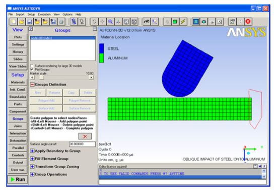
Any nodes, faces or elements that are enclosed by the polygon are highlighted, and you are prompted to accept the selection of nodes or faces. These are then added to the current group.
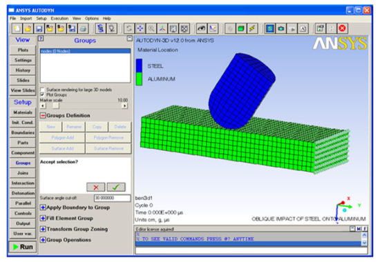
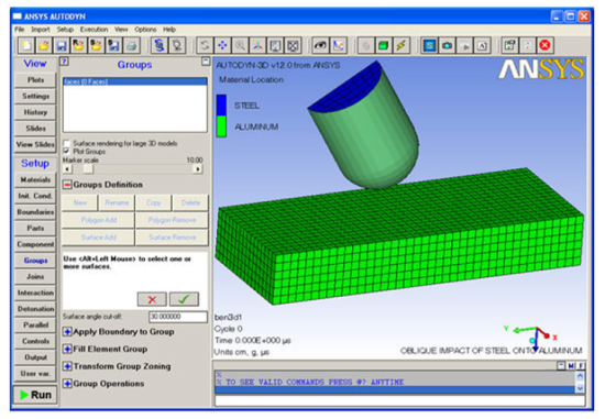
For face groups, an alternative surface selection method exists. The selection is made by interactively picking a face element in the graphics window. Any faces that are joined to the selected face and have a normal angle between the two faces of less than a user specified value are then added to the group.
For example, selecting an element on the side of a cube would add all faces on that side of the cube. By setting the surface angle cut-off to a sufficiently large value, curved surfaces may also be selected, as shown in the example below, where the curved surface of the projectile has been added to a group.
Once a group is defined, a number of operations can be performed, depending on the type of group.
Groups
A Group is a selection of nodes, faces or elements to which you can perform operations such as applying boundaries and filling.
This panel lets you define Groups and use them to perform various operations.
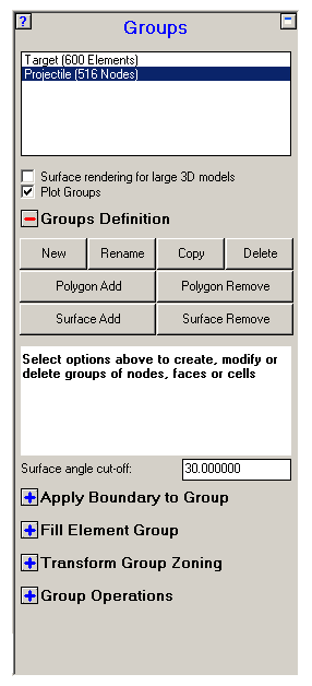
- Group List
Displays a list of the Groups you have defined, together with their type (node, face or element) and the group size. You can select a Group in this list.
- New
Create a new Group.
- Rename
Rename an existing Group.
- Delete
Delete a Group
- Review
Review existing Groups.
Groups Definition
- Polygon Add
Click this button to interactively define a polygon; any nodes, faces or elements that lie within the 2D polygon are added to the selected Group.
Select the polygon points using the Alt+left mouse button. To delete the last polygon point, use Shift+left mouse button. To complete the polygon, use Ctrl+left mouse button.
After completing the polygon, the selected nodes or faces are displayed. Click the
 button to accept this selection, and add to the
current Group. At any stage, the
button to accept this selection, and add to the
current Group. At any stage, the  button may be used to cancel the process.
 To be able to use the Polygon Add option you should use the zoom option,
 available from the toolbar of Autodyn.
 Note: The Polygon Add option is not available (greyed-out) when you have zoomed into the model using the rubber-band option using Ctrl+left mouse button. The Polygon Add option is also not available when the Shell Thickness plot is active.
- Polygon Remove
Click this button to interactively define a polygon; any nodes, faces or elements that lie within the 2D polygon are removed from the selected Group.
Select the polygon points using Alt+left mouse button. To delete the last polygon point, use Shift+left mouse button. To complete the polygon, use Ctrl+left mouse button.
After completing the polygon, the selected nodes or faces are displayed. Click the
button to accept this selection, and add to the
current Group. At any stage, the button may be used to cancel the process. To be able to use the Polygon Remove option you should use the zoom option,
available from the toolbar of Autodyn. Note: The Polygon Remove option is not available (greyed-out) when you have zoomed into the model using the rubber-band option using Ctrl+left mouse button. The Polygon Remove option is also not available when the Shell Thickness plot is active.
- Surface Add
Click this button to choose a surface and add its nodes, faces or elements to the selected Group.
Select a face using Alt and the left mouse button. Any faces that are joined to the selected face and have a normal angle between the two faces of less than a value you specify are then added to the group. For example, selecting an element on the side of a cube would add all faces on that side of the cube. By setting the surface angle cut-off to a sufficiently large value, curved surfaces may also be selected.
After selecting a face, the corresponding surface is highlighted in the graphics window. Click the
button to accept this selection or continue adding
further surfaces with the Alt+left mouse button.
At any stage, the button may be used to cancel the process. - Surface Remove
Click this button to choose a surface and remove its nodes, faces or elements to the selected Group.
Select a face using Alt and the left mouse button. Any faces that are joined to the selected face and have a normal angle between the two faces of less than a value you specify are then removed from the group. For example, selecting an element on the side of a cube would remove all faces on that side of the cube. By setting the surface angle cut-off to a sufficiently large value, curved surfaces may also be selected.
After selecting a face, the corresponding surface is highlighted in the graphics window. Click the
button to accept this selection or continue adding
further surfaces with Alt+left mouse button. At
any stage, the button may be used to cancel the process. - Surface Angle Cut-Off
Enter a cut-off angle (in degrees). Only faces with an angle between the normal and a neighbor face's normal of less than this value will be included in a surface selection.
- Apply Boundary to Group
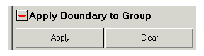
- Apply
Apply a boundary condition to a node or face Group.
- Clear
Remove a boundary condition from a node or face Group.
- Fill Element Group

- Material
Fill the selected element Group with a material.
- Velocity
Assign a velocity to the selected element Group.
- Initial Conditions
Assign initial conditions to the selected element Groups.
- Transform group zoning

- Translate
Translate (move) the current group.
- Rotate
Rotate the current group.
- Scale
Scale the current group.
- Group Operations
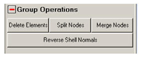
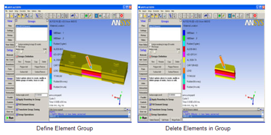
- Delete Elements
Delete all elements within a selected Group. Select the Group containing the elements to delete and click . The elements are deleted from the model.
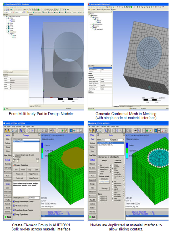
- Split Nodes
Split nodes across material boundaries within a selected group. Autodyn will search through all elements in the selected group and identify nodes that are connected to elements (through the connectivity table) with different materials. Each node connected to more than one material will be replicated by the number of connected materials, while retaining the same physical location. The connectivity of each associated element will be updated.
The option is useful for generating a sliding interface between two materials and enforcing a conforming mesh (coincident nodes) between the material interface at the start of the simulation.
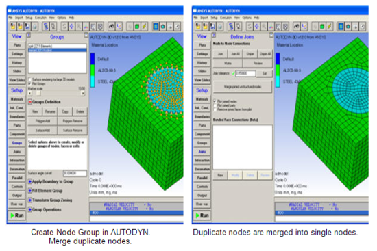
- Merge Nodes
Merge coincident (joined) unstructured nodes into a single unstructured node. This option is similar to using the "Merged joined nodes" option on the Join panel; with this option only the nodes that are part of the node group will be merged.
This option will increase the robustness in many applications involving joins.
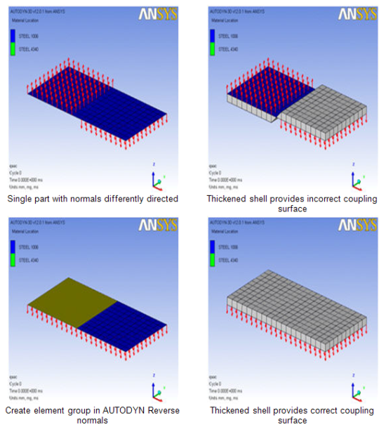
- Reverse Shell Normals
Reverse the shell element normal of a selected group of shell elements.
This option has to be used when not all element normals of a shell part point in the same direction and Euler-Lagrange coupling is used with thickened shells.