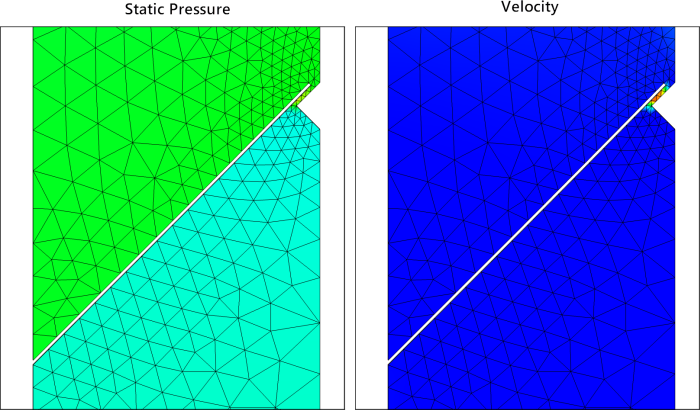
This tutorial uses an example of a reed valve — such as might be used in a two-stroke engine — to demonstrate how to set up and run an FSI co-simulation using System Coupling in Workbench.
The case includes a stainless-steel reed valve that is anchored to the valve housing, and a suction stopper at the free end of the reed. The modeled case includes a symmetry condition near the free end of the reed, and inlet and outlet conditions that drive air flow through the valve. Although the inlet pressure follows a sinusoidal variation with a period of 0.02 [s], the simulation includes only the first half of the period, during which the inlet pressure is positive and drives flow through the valve.
This case is set up as a Fluid-Structure Interaction (FSI) co-simulation with two-way data transfers, as follows:
The motion of the reed valve is modeled using a Mechanical Transient Structural analysis system.
The motion of the air in the closed cavity is modelled using a transient Fluid Flow (Fluent) analysis system.
A coupling interface, which is where data is transferred between the two solvers, is defined on the three faces of the reed valve that are in contact with the air.
- Data Transfers
The co-simulation involves two data transfers of the following quantities:
Force: Force data from the motion of the air are received by the transient structural analysis, which models the structural behavior over time.
Incremental Displacement: Displacement data from the motion of the reed valve are received by the fluid-flow analysis as it solves the fluid behavior over time.
- Transient Settings
The oscillation of the valve is dependent on time, so appropriate time values have been specified for the transient co-simulation:
End Time is the total time observed for the analysis. The time duration is set to 0.01 s, which is enough time to observe the reed valve open and close once.
When setting up a transient analysis, make sure that you choose a time duration that will allow you to observe the behavior of interest in the system.
Time Step Size is the length of the time increments that you are solving within the transient analysis. The time step is set to 0.0001 s, which is fine enough to resolve the high-speed flow through the valve opening.
When setting up a transient analysis, make sure you choose a time step that works for the physics you are solving. Too large a time step will miss the behavior of the system, and too small a time step will be computationally expensive.


