Moving Parts in an Assembly
You can set up virtual mechanisms by defining mating conditions in your assembly. These relationships are solved when you move any related part in the assembly.
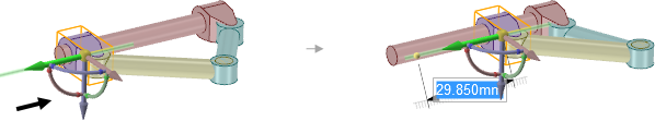
The example shows a slider mechanism. The purple component is moved in the direction of the black arrow shown on the left in the image below.
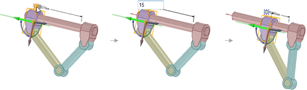
When you move a component that has a mating condition, the Move handle is positioned at the constraint and the axes that are constrained can't be moved. If the assembly constraints only allow movement in one direction, then that direction will be automatically selected. For example, if you move a component with a Center Axes assembly constraint, the Move handle is positioned on the axis and you can only move the component in directions that will keep the axes aligned.
You can solve assembly mechanisms by changing ruler dimensions or annotation dimensions, and they can be saved as groups for modification. The images below show movement of the Slider Mechanism assembly that is driven by a change to the annotation dimension.