Maps both input signal S1 and S2 to the merged axis of abscissae. If the axes of abscissae are different the signal will be interpolated to the additional abscissa values by interpolation type ty and slopes dstart and dend (see function Interpolate for more information). In this case the signal which will be interpolated must be real.
Syntax
mapping(S1,S2,ty,dstart,dend])
Types
| Variable Name | Value Type | Variable Type | ||
|---|---|---|---|---|
| Arguments: | S1 | real, complex | signal, xy-data | |
| S2 | real, complex | signal, xy-data | ||
| ty | LINEAR, QUAD, SPLINE | |||
| dstart | real | scalar | ||
| dend | real | scalar | ||
| Result: | real, complex | signal | ||
Calculator Input
Use the button to complete the operation.
Examples
| ID | Description | Type | Value | Expression | |
|---|---|---|---|---|---|
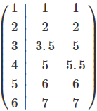
| S1 | REAL SIGNAL |  | signal([1,2,4,5,6],[1,2,5,6,7]) | ||
| S2 | REAL SIGNAL |  | signal([1,2,3,5,6][1,2,5,6,7]) | ||
| d_start | REAL | 0 | 0 | ||
| d_end | REAL | 0 | 0 | ||
| mapS1S2 | Result | REAL SIGNAL |  | mapping(S1, S2, LINEAR, d_start, d_end)) | |


