oSP3D needs to have a definition of the connectivity (for visualization and spatial association), including the type of field data (1D, 2D, 3D, or FEM) and the associated data for each design variation.
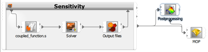
Here is the workflow for a DOE:
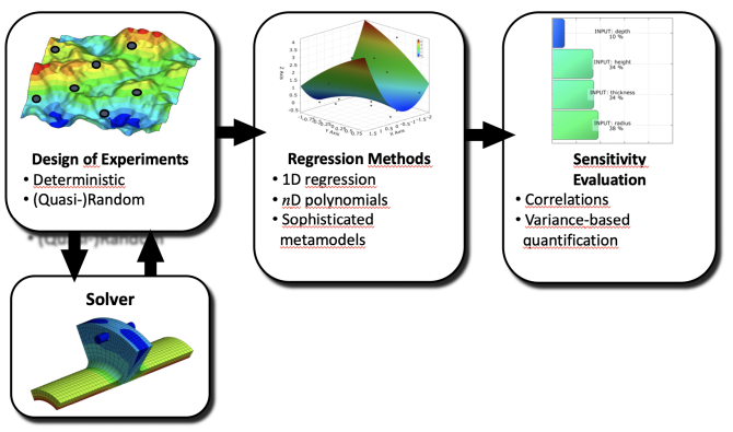
In optiSLang, you start by defining a solver chain and the parameter properties.
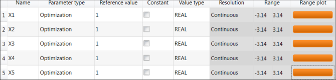
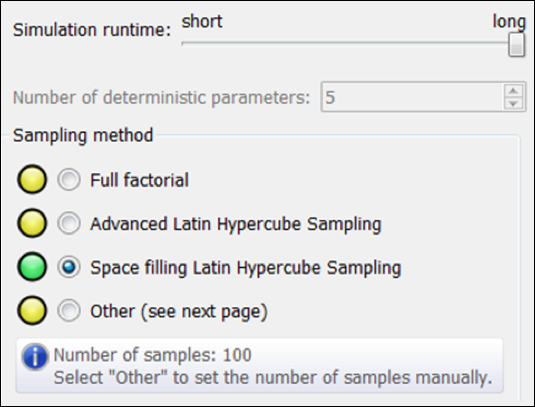
You then drop the sensitivity wizard on the final solver chain and define the lower and upper bounds of the input variables. optiSLang recommends the sampling method and sample number based on the chosen solver runtime and number of parameters.
optiSLang then creates a sensitivity system that generates a DOE scheme and executes the corresponding solver runs. The statistical postprocessing calculates correlations for the available designs even while the DOE is running. The MOP is generated within an additional node after the DOE is finished.
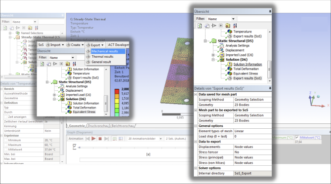
When dealing with DOEs, you must define the output files that are produced by the solver:
Ansys Mechanical has an ACT extension for oSP3D that can prepare the 3D output (meshes and data fields).
Ansys LS-DYNA has LS-PrePost that can prepare the 3D result data (data fields).
For signal data, you can use optiSLang's capabilities to import signals from text files into the OMDB database file.
For all other applications, you must write a converter or use the embedded scripting abilities to produce output that oSP3D can import.
The following image shows the ACT oSP3D extension for Ansys Mechanical:
For standard formats, you can use optiSLang integration nodes to import the data and automatically perform a standard analysis. This includes:
Ansys Mechanical results if mesh topology was not changed
2D performance maps when using encapsulated DOE systems
Signals in MOP node
For other cases, the oSP3D standalone GUI must be open and the data must be imported manually.
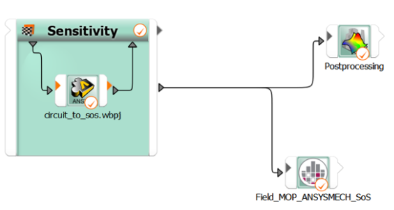
The following image shows the Ansys Mechanical oSP3D integration node in the optiSLang workflow.