


Prerequisites
This documentation assumes that you understand the concept and use of the application’s existing Spot Weld feature. The Weld Group (Beta) feature is like the existing Spot Weld control, but has a few notable differences, including:
The Spot Weld feature requires a Spot Weld for each weld. The Weld Group (Beta) groups numerous spot welds by the parts/bodies they connect.
The Spot Weld feature constructs "mesh dependent welds." The Weld Group (Beta) provides an option to construct the welds as mesh dependent or as mesh independent (as discussed in the Understanding Mesh Dependent and Mesh Independent Definitions topic).
The Spot Weld feature requires that you define the spot welds in SpaceClaim or DesignModeler. Or, that you at least create the spot weld vertices to be used (before entering Mechanical). There is no current method to create a Spot Weld in Mechanical.
Currently, you cannot import spot welds defined in SpaceClaim or DesignModeler into Mechanical as a group, however, there is an existing script that imports point locations.
Activate Beta Options to turn on the feature.
Overview
The Weld Group connection feature (folder) enables you to manage a group of spot welds that connect multiple surface body parts. This folder provides properties to either import predefined spot welds or to manually create individual spot welds. An example of an imported group of spot welds is illustrated below. Once imported, the application automatically creates Weld Connection objects. The data for the Weld Connection object is displayed in the Details pane. The data for each spot weld is displayed in the Weld Connection Worksheet. Data includes the source and target bodies of the weld and properties relating to the set of welds in the Details view and an identifier and a coordinate location for each spot weld in the Worksheet.
When you select a Weld Connection object, the application highlights the corresponding spot welds for the given connection in the Geometry window, as illustrated below.
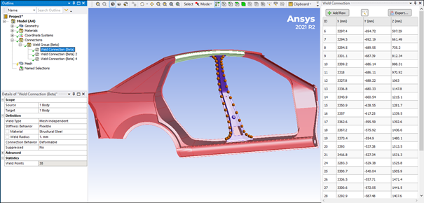
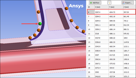
In addition, the Source body displays in red, the Target body displays in blue, and an orange ball displays each spot weld. Selecting a row in the Weld Connection Worksheet highlights the individual spot welds in green.
Understanding Mesh Dependent and Mesh Independent Definitions
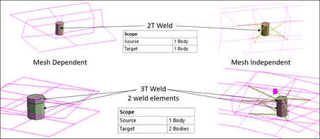
The spot welds are assigned a type, either Mesh Dependent or Mesh Independent (default). These settings are specified by the Weld Type property using the Weld Connection objects. The Weld Type, along with the setting for Stiffness Behavior determines how the spot welds will be modeled when generating the mesh.
In the following example, you can see:
The weld element is modeled the same for mesh dependent and mesh independent weld types. Using the Stiffness Behavior property, you specify the element as a Flexible (beam), Stiff Beam or Rigid (beta).
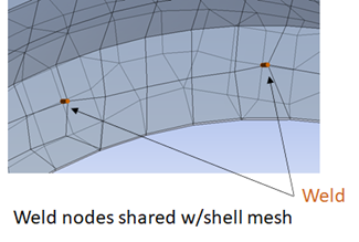
For each mesh dependent weld, nodes are inserted during mesh process so that the weld element connects directly to the shell mesh on the Source and Target bodies. That is, each node of the weld element is shared with the shell elements.
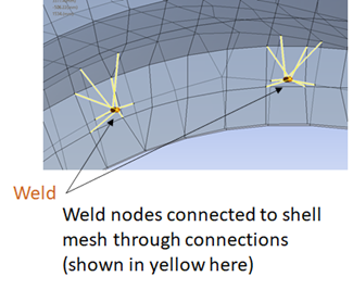
For mesh independent welds, the shell mesh and weld elements are generated independently, and the weld element nodes are not shared with the shell mesh. The Connection Behavior property controls how the nodes of the weld elements are tied to the shell mesh. Options for this property include Deformable and Rigid. The connection between the weld elements and the shells is displayed as a yellow spider web.
| MESH DEPENDENT | MESH INDEPENDENT |
|
|
|
Simply put, for mesh dependent welds, the nodes of the spot weld elements are directly connected to the shell mesh. For mesh independent welds, the spot weld elements are connected to the shell mesh either through contact or rigid connections based on property settings.
Spot Weld File Format
Prior to importing your spot weld file, you must ensure that the file you use follows the conventions used by Dyna or Primer, as shown in this example:

As illustrated, the spot weld files have the following properties:
Asci file where text is separated by spaces (*.csv type format)
Each line represents a spot weld, and:
The first entry should be “SPOTWELD.”
The second entry is the id of the weld.
The third entry is the X position of the weld.
The fourth entry is the Y position of the weld.
The fifth entry the Z position of the weld.
Part identifiers are optional. If part ids are desired, the 6th entry should specify “PARTS” and then the seventh to nineth entries indicate the parts of the weld.
If parts are used the part ID in the weld file need to be encoded in the names of the bodies. For example, if the weld file contains part IDs (54325,54625,54525), the body names would need to appear as follows, where the body names include the part IDs at the end of the body name.
Weld Thickness
Only two thickness (2T) and three thickness (3T) welds are supported:
Importing Weld Connections
To import Weld Group Connections:
Highlight the Connections object and then select the Weld Group option from the Connect group of the Connections Context tab to insert a Weld Group object. An example of the object’s Details is show here. Many properties have default values.
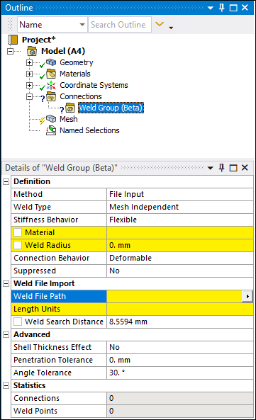
Specify highlighted properties. Properties include:
Material
Weld Radius
Length Units
Select the entry field of the Weld File Path property and the arrow menu display option. A dialog opens.
Navigate to and select the file you wish to import from the Open dialog.
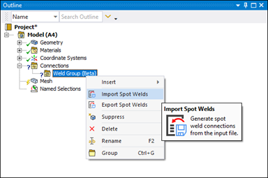
Right-click the Weld Group object and select the Import Spot Welds.
Select each Weld Connection object and review all property definitions as well as the data provided in the Weld Connection window. Perform corrections as needed.
Manually Creating Weld Group Connections
To create Weld Connections manually:
Highlight the Connections object and then select the Weld Group option from the Connect group of the Connections Context tab to insert a Weld Group object. An example of the object’s Details is show here. Many properties have default values.
Set the Method property to Manual.
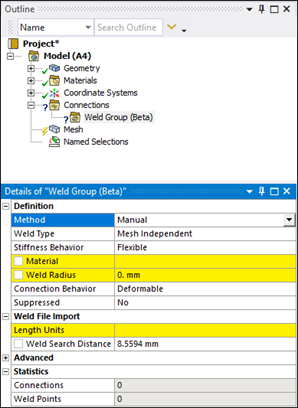
Specify highlighted properties. Properties include:
Material
Weld Radius
Length Units
Right-click the Weld Group object and select Insert > Weld Connection.
Specify the desired surface bodies for the Source and Target properties.
Modify object properties as needed.
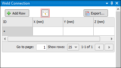
When inserted, the Weld Connection window displays automatically. The Hit Point Coordinate option, highlighted below, is active by default. This option enables you to set a coordinate location. As show in the next step, the option displays the exterior coordinates of the model as the cursor is moved across the model.
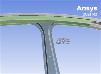
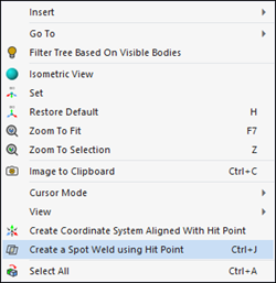
Coordinate labels appear where you place the cursor. Select the locations for your spot weld, right-click, and select the option Create Spot Weld using Hit Point. The data table automatically populates each coordinates each time a spot weld is specified.
This feature is functional on faces only. It is not functional on edges or line bodies.
Continue creating sport welds as desired.
Weld Group Object Properties
The properties of the Weld Group folder specify values for all Weld Connection child objects.
| Category | Property/Options/Descriptions |
|---|---|
|
Definition |
Method: Specify to import spot weld from a text file or to create them manually. Options include File Input (default) and Manual. Stiffness Behavior: Depending upon the Weld Type setting, select a (element) stiffness behavior, including:
Material: Specify desired material for all (child object) weld connections. Weld Radius: When the Stiffness Behavior is set to Flexible or Stiff Beam, beam elements are created during mesh generation. The beams automatically receive a circular cross section defined for them where the radius is set by this property. In other words, this Weld Radius is the circular radius representing the weld. Connection Behavior: This property displays when the Weld Type property is set to Mesh Independent. The Connection Behavior (for the yellow lines) is defined as either:
Snap To Edge Tolerance: This property displays when the Weld Type property is set to Mesh Dependent. The application uses this tolerance (+/-) value during the meshing process to place or “snap” a weld point to a boundary (edge) as opposed to placing the weld point on a face that is close to the boundary (closer than defined tolerance). This helps makes sure that small edges are not created. Suppressed: Options include Yes or No (default). This property enables you to remove (and re-include) the object from analysis processes. |
|
Advanced |
Shell Thickness Effect: This property enables you to include the thickness of the surface body during contact calculations. Instead of contact being detected on the face of the surface body, contact will be detected at a distance that is half the thickness from the face. Penetration Tolerance: Specify a desired Penetration Tolerance value. Angle Tolerance: This property enables you to specify a tolerance (+/-) value that the desired/ideal orthogonal angle of each
spot weld may deviate. The default value is |
|
Statistics |
Connections: Total number of Weld Connection objects included in group. Weld Points: Total number of spot weld connections included in group. |
Weld Connection Object Properties
The properties of the Weld Connection object specify values for the associated grouping of spot welds.
| Category | Property/Options/Descriptions |
|---|---|
|
Scope |
Source: Display/select the source side surface body for the weld connection. This geometry can be manually selected or automatically generated. Target: Display/select the target side surface body for the weld connection. This element can be manually set or automatically generated. |
|
Definition |
Method: Specify to import spot weld from a text file or to create them manually. Options include File Input (default) and Manual. Stiffness Behavior: Depending upon the Weld Type setting, select a (element) stiffness behavior, including:
Material: Specify desired material for all (child object) weld connections. Weld Radius: When the Stiffness Behavior is set to Flexible or Stiff Beam, beam elements are created during mesh generation. The beams automatically receive a circular cross section defined for them where the radius is set by this property. In other words, this Weld Radius is the circular radius representing the weld. Connection Behavior: This property displays when the Weld Type property is set to Mesh Independent. The Connection Behavior (for the yellow lines) is defined as either:
Snap To Edge Tolerance: This property displays when the Weld Type property is set to Mesh Dependent. The application uses this tolerance (+/-) value during the meshing process to place or “snap” a weld point to a boundary (edge) as opposed to placing the weld point on a face that is close to the boundary (closer than defined tolerance). This helps makes sure that small edges are not created. Suppressed: Options include Yes or No (default). This property enables you to remove (and re-include) the object from analysis processes. |
|
Advanced |
Shell Thickness Effect: This property enables you to include the thickness of the surface body during contact calculations. Instead of contact being detected on the face of the surface body, contact will be detected at a distance that is half the thickness from the face. Penetration Tolerance: Specify a desired Penetration Tolerance value. Angle Tolerance: This property enables you to specify a tolerance (+/-) value that the desired/ideal orthogonal angle of each
spot weld may deviate. The default value is Snap To Edge Tolerance: This property displays when the Weld Type property is set to Mesh Dependent. The application uses this tolerance (+/-) value during the meshing process to place or “snap” a weld point to a boundary (edge) as opposed to placing the weld point on a face that is close to the boundary (closer than defined tolerance). This helps makes sure that small edges are not created. |
|
Statistics | Weld Points: Total number of spot weld connections for the object. |