This wizard is primarily focused on the setup steps and includes the following tabs:
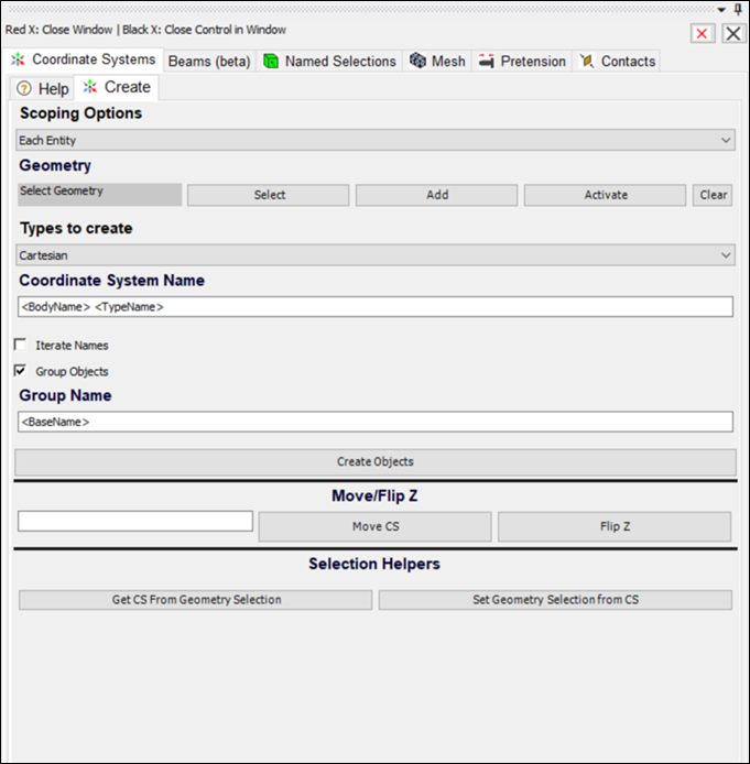
Coordinate Systems
The purpose of this tab is to create multiple coordinate systems.
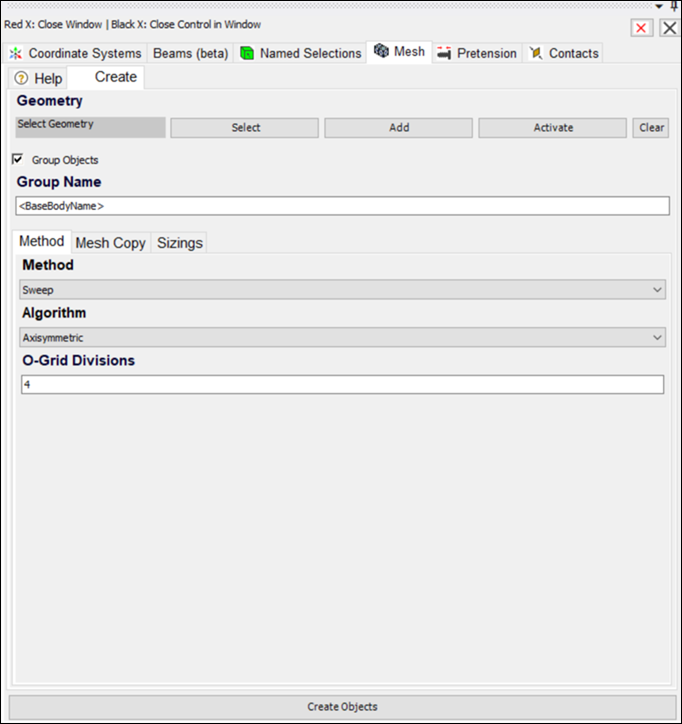
Mesh
The purpose of this tab is to create mesh controls that are typically used for meshing of bolt hardware, including:
- Mesh Copy
Copy a mesh from one body to multiple other bodies.
- Axisymmetric Sweep
Create an organized mesh for components that can be swept around an axis.
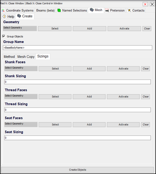
- Mesh Sizing
Sizing of different user or auto-identified regions of a bolt. There are options available to include sizing for shank, thread, and seat faces of the bolt body. If the shank, thread, and seat faces are not selected explicitly, these are automatically identified for bolts selected in the geometry tab.
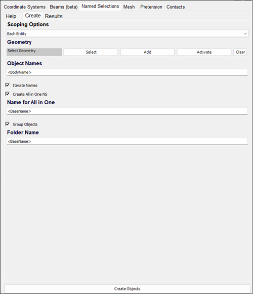
Named Selections
The purpose of this tab is to create Named Selections of multiple items. Named selections of each individual entity in the selection can be created easily.
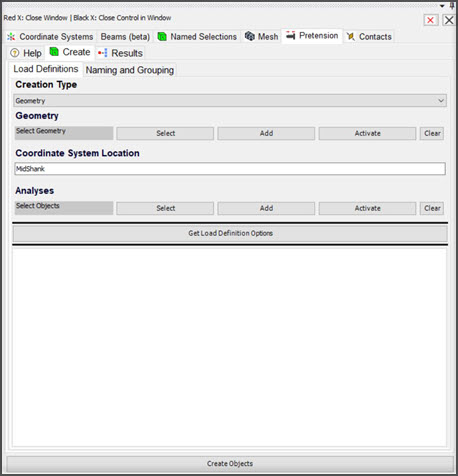
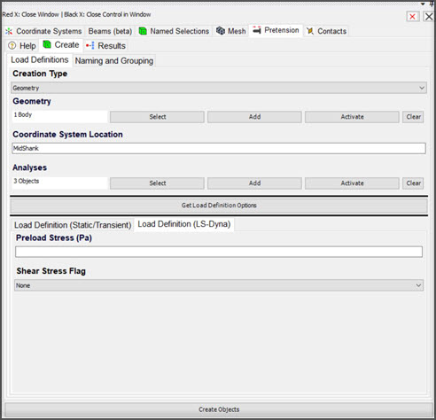
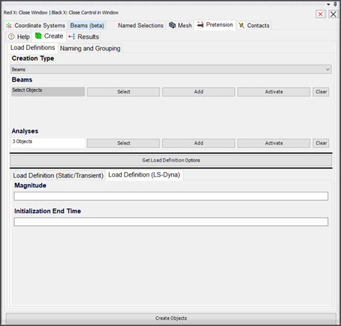
Pretension
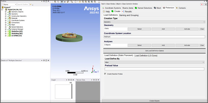
The purpose of this tab is to create bolt Pretension objects and associated results probes. Bolt pretension can be created for 3D geometry or beams, and the location of the pretension split can be directly input or inferred from geometry recognition with keyword inputs. The supported analysis types include Static, Transient, and LS-DYNA.
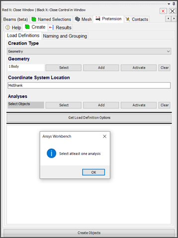
It is mandatory to select at least one analysis object in the Pretension wizard. Multiple analysis objects can be selected. Depending on the type of selected analysis (i.e. Static, Transient, or LS-DYNA), different load definition tabs are added to the panel.
Note: Click Get Load Definition Options every time the analysis objects are altered. For LS-DYNA analyses, the load definition options are updated, hence supporting the geometry and beam connection scoping.
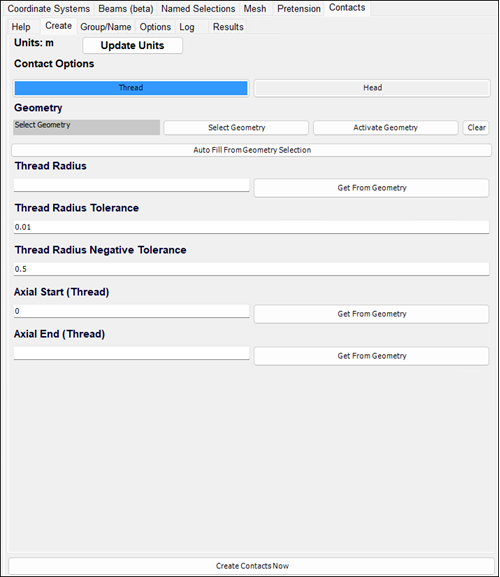
Contacts
The purpose of this tab is to create bolt contact regions. This includes separate contacts for the Head and Thread regions. There are many dimensional inputs for you to manually input or auto-detect. These inputs are then used in Named Selection worksheet logic to identify the correct regions in the model for the contacts.