


*BOUNDARY_NON_REFLECTING
Specifies impedance boundaries. Impedance boundaries can only be applied on solid elements in LS-DYNA.
Card
SSID = ID of segment on whose nodes the boundary is applied (see *SET_SEGMENT bellow).
AD = 0.0 (default) for setting the activation flag for dilatational waves to on.
AS = 0.0 (default) for setting the activation flag for shear waves to on.
*BOUNDARY_SLIDING_PLANE
Defines a boundary plane for sliding symmetry.
Note: The normal is defined as the z-axis vector of the coordinate system defined in Mechanical.
NSID = ID of the set of nodes to which the boundary is applied
VX = X component of vector defining normal.
VY = Y component of vector defining normal.
VZ = Z component of vector defining normal.
COPT =
0 if the Option is set to node moves on normal plane.
1 if the Option is set to node moves only in vector direction.
*RIGID_WALL_PLANAR
The Rigid Wall object provides a simple way of treating contact between a rigid surface and nodal points of a deformable body called contact nodes. The Rigid Wall can be scoped to Geometry or Named Selections. You can exclude specific areas of the model from the Rigid Wall contact.
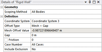
The Offset Type property can be set under the Rigid Wall object. This property provides the option to specify an offset for the rigid wall plane along the normal Z direction of the selected coordinate system.
| Offset Type Options | Description |
| None | The default value of the rigid wall plane is positioned at Z = 0 in the selected coordinate system. |
| Mesh | The rigid wall plane is positioned at Z = Mesh Offset Value in the selected coordinate system, where Mesh Offset Value is calculated as the distance delta Z in the negative Z direction to the furthest mesh node of the scoped geometry. |
| Gap | The rigid wall plane is positioned at Z = -Gap in the selected coordinate system, where Gap is a user-defined delta Z applied in the selected coordinate system. |
| Mesh + Gap | The rigid wall plane is positioned at Z = Mesh Offset Value - Gap in the selected coordinate system, where Mesh Offset Value is calculated as the distance delta Z in the negative Z direction to the furthest mesh node of the scoped geometry and Gap is a user-defined delta Z applied in the selected coordinate system. |
Note: A valid mesh must be generated for offset types of Mesh or Mesh + Gap, otherwise the property is shown as invalid, and no offset is applied.
NSID = ID of the set of nodes to which the boundary is applied.
XT, YT, ZT, XH, YH, ZH are calculated from the Coordinate System definition; the normal Z of the coordinate system is the normal to the plane.
FRIC = Friction.