To include PCB attachments in your Ansys Icepak model, selectMacros
 Geometry
 PCB . You can then select one of the following features:
Wedgelock, Bolt, or
Stiffener.
PCB . You can then select one of the following features:
Wedgelock, Bolt, or
Stiffener.
Wedgelock
Wedgelocks are used to define a location on the board where the board is clamped to a heat sink or cold plate at a defined temperature. Wedgelocks can be anywhere on the board and can have its own cold plate temperature. Wedgelocks are used to generate a contact force between the board edge and a cold plate. Therefore, the heat is transferred from the board on the side opposite of the wedgelock to a cold plate or heat sink. This enhanced contact force increases the efficiency of the heat transfer between the board and cold plate.
The procedure for adding a wedgelock to your model is as follows:
Go to Macros
 Geometry
 PCB
PCB
 Wedgelock to display the Create
Wedgelock panel.
Wedgelock to display the Create
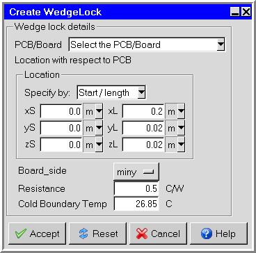
Wedgelock panel.Click the arrow in PCB/Board text box to select a PCB/Board. Click Accept in the drop-down list.
Enter the wedgelock dimensions using either Start/length or Start/end specifications.
Select the place where the device is clamped to the board in the Board_side drop-down list.
Enter the thermal Resistance of the device.
Next enter the temperature of the surface the board is being clamped to in the Cold Boundary Temp edit box.
Click the Accept button at the bottom of the panel to apply your changes and close the panel.
Bolt
Bolts are used to define a location on the board where the board is bolted to a heat sink or cold plate at a defined temperature. Bolts can be anywhere on the board and can have its own cold plate temperature.
The procedure for adding a bolt to your model is as follows:
Go to Macros
 Geometry
 PCB
PCB
 Bolt to display the Create Bolt panel.
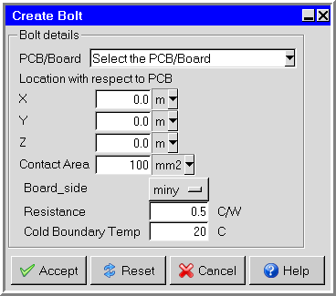
Click the arrow in PCB/Board text box to select a PCB/Board. Click Accept in the drop-down list.
Enter the location of the bolt with respect to the PCB in the X, Y, and Z text boxes.
Enter the contact area of the bolt in the Contact Area text box.
Select the side of the board the bolt is attached to in the Board_side drop-down list.
Enter the thermal Resistance of the bolt.
Next enter the temperature of the surface the bolt is being clamped to in the Cold Boundary Temp edit box.
Click the Accept button at the bottom of the panel to apply your changes and close the panel.
Stiffener
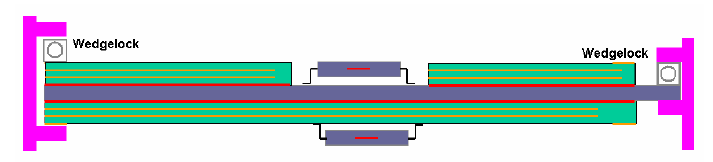
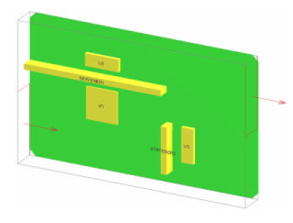
Stiffeners are items that are either bolted or bonded to the board surface. They are represented three-dimensionally on the board as well as in the air solution. Stiffeners enhance the heat transfer over the board by adding a thermal path from the board surface, across the bond or bolted interface, three-dimensionally through the stiffener and back to the board surface. Stiffeners also impact the air flow over the board. They can be used to direct air flow across the board. Heat is also transferred from the sides of the stiffener to the air, acting like a fin.
Stiffeners can be used to represent any rectangular shaped homogeneous object on the board. This could be an aluminum piece that spans the board to add structural rigidity to the board. It could also be sheet metal used to direct air flow across the board. The stiffener impacts both the air flow over the board as well as the heat transfer in the board. The stiffener can be bolted at specific locations or it can be continuously bonded to the board. Convection is accounted from all surfaces of the stiffener to the local air. Therefore they act as a fin on the board adding convective surfaces area to the board. The figure below shows such an example.
The procedure for adding a stiffener to your model is as follows:
Go to Macros
 Geometry
 PCB
PCB
 Stiffener to display the Create Stiffener
panel.
Stiffener to display the Create Stiffener
panel.Click the arrow in PCB/Board text box to select a PCB/Board. Click Accept in the drop-down list.
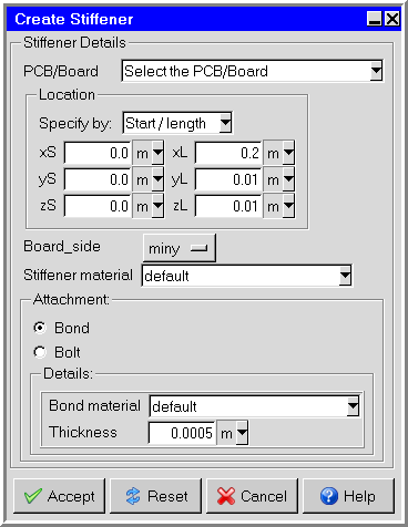
Enter the stiffener dimensions using either Start/length or Start/end specifications.
Select the place where the stiffener is clamped to the board in the Board_side drop-down list.
Select the Stiffener material in the drop-down list.
Select Bond or Bolt attachment. The Details group box will change depending on your selection.
If you select Bond, then enter the Bond material and Thickness in the Details group box.
If you select Bolt, then enter the Resistance, Tie Position, and values in the Curve specification panel in the Details group box. The Curve specification panel is displayed when you click the Edit button and select Text editor. The values represent the tie down point and the position of the tie down along the length of the stiffener.
Click the Accept button at the bottom of the panel to apply your changes and close the panel.