


This contains rigid body transformation values (center of gravity translations and euler parameters) over time. Please note that these transformations are applied after any yaw pitch roll rotations and/or any center of gravity offsets specified in the EnSight Rigid Body version 1 file, or any of the pre-transformations specified in the EnSight RigidBody version 2 file. These transformations first do the euler parameter rotations then the translations. While not required, .eet, is the normal extension given to this file. It is referenced for EnSight parts via the EnSight Rigid Body file. It can also be referenced from readers. The Nastran reader .mop file, and the STL reader .xct are examples of this.
For a concise description of euler parameters, see the following, some of which is discussed below.
Eric W. Weisstein. "Euler Parameter." From MathWorld--A Wolfram Web Resource. http://mathworld.wolfram.com/EulerParameters.html
Note the following:
The first line needs to be exactly as shown.
Ens_EulerThe second section consists of two lines. The first of which must be exactly:
NumTimes:and the second of which must contain one integer indicating the number of times,
nt
contained in the file.
The third section consists of two lines. The first of which must be exactly:
NumTrans:
and the second of which must contain one integer indicating the number of transformations,
ntx
contained in the file.
The fourth section must begin with a line that is exactly:
Titles:
and must have
ntxnumber of lines - each containing the title associated with a transformation. These are the titles that .erb, .mob, and .xct files reference as they associate parts with rigid body transformations.The rest of the file consists of
nttime step sections with the first line being exactly:Time Step
the next line containing only a single float which represents the time value, and the next
ntxlines containing 7 floats representing the 3 translations in x, y, z and the 4 euler parameters. So the way this would work is as follows. The transformations from the Rigid Body File are applied: first the yaw pitch roll rotations (if any specified) then second, the center of gravity offsets (if any specified) and then the transformations from this Euler Parameter file: the euler parameter rotations about 0,0,0 and then the translations.
So, here is how you might use this. First put in any pre-rotations into the Rigid Body File (if any alignment is needed, this is not normally needed), then put a translation in the Rigid Body File in order to move the center of rotation of the part to the origin (0,0,0) and then do the Euler rotation from the Euler Parameter file, and then move the part back to its original location from the Euler Parameter file. The net effect is to mathematically rotate the part about its center of rotation.
The euler parameters, eo, e1, e2, and e3 describe a finite rotation angle of ϕ as
follows:
and a normalized, scaled unit vector, n, about which the rotation occurs.
and eo, e1, e2, and
e3 form a quaternion in scalar-vector representation 
and, since, Euler's rotation theorem states that an arbitrary rotation
may be described by only three parameters, the four quantities must be related 
Important: If your four euler parameters don't satisfy these equations you may get odd non-linear rotational behavior and scaling of your geometry.
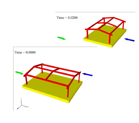
Suppose we want to rotate frame and base in the frame dataset (included in your EnSight install at $CEI/ensight242/data/frame) about the Y-axis in several timesteps. The frame dataset is static, that is, it has no timesteps. But, using the rigid body rotation files, we will make the parts transient in time.
The frame case file is modified by adding one line after the model line which indicates the EnSight rigid body (.erb) filename.
model: frame.geo
rigid_body: motion.erb
The motion.erb file might look as follows:
EnSight Rigid Body
version 1.1
names
2
"3d space frame" "simple_euler_y.eet" "Frame" "1.0" "0.0" "0.0" "0.0" "xyz" "0.0" "0.0" "0.0"
"frame base" "simple_euler_y.eet" "Frame" "1.0" "0.0" "0.0" "0.0" "xyz" "0.0" "0.0" "0.0"
This .erb file names the euler (.eet) file: simple_euler_y.eet which is as follows:
Ens_Euler
NumTimes:
5
NumTrans:
1
Titles:
Frame
Time Step:
 0.0
 0.0 0.0 0.0 1.0 0.0 0.0 0.0
Time Step:
 0.01
0.0 0.0 0.0 0.92388 0.0 0.38268 0.0
Time Step:
 0.02
 0.0 0.0 0.0 0.707 0.0 0.707 0.0
Time Step:
 0.03
 0.0 0.0 0.0 0.3827 0.0 0.92390 0.0
Time Step:
 0.04
 0.0 0.0 0.0 0.0 0.0 1.0 0.0
Notice that the Euler parameters are for 5 rotations about the Y-axis, 0, 45, 90, 135, and 180 degrees. The four euler parameters are
cos( ϕ / 2 ), 0.0, 1.0*sin( ϕ / 2 ), 0.0
In this simple example we now have changed a static dataset into a transient dataset with 5 timesteps. Notice that the .erb file has no translations. The frame will rotate about one of the corners located at 0.,0.,0. If you want the Frame part to rotate about the part centroid, then enter the centroid location (use a translation of 190,56,148). The .erb applies the negative of the values you enter to move it over to the centroid prior to applying the Euler rotation.
EnSight Rigid Body
version 1.1
names
2
"3d space frame" "simple_euler_y.eet" "Frame" "1.0" "190." "56." "148." "xyz" "0.0" "0.0" "0.0"
"frame base" "simple_euler_y.eet" "Frame" "1.0" "0.0" "0.0" "0.0" "xyz" "0.0" "0.0" "0.0"
and each of the timesteps in the .eet file should translate back to the original location by entering the same 190,56,148 values to move the part back to its original location after the application of the Euler rotation, as follows.
Ens_Euler
NumTimes:
5
NumTrans:
1
Titles:
Frame
Time Step:
 0.0
 190.0 56.0 148.0 1.0 0.0 0.0 0.0
Time Step:
 0.01
 190.0 56.0 148.0 0.92388 0.0 0.38268 0.0
Time Step:
 0.02
 190.0 56.0 148.0 0.707 0.0 0.707 0.0
This is useful for showing the translational and rotational motion of a rigid body. This is also useful for steady-state flows that include one solution that may have a rotational part(s) that you wish to animate over time. You can create an euler file that accurately rotates the part over time as well as the flow field around it, and then trace pathlines through this rotating flowfield, because the velocity and other vector variables are rotated along with the geometry.
Another, more complex sample file might look like the following:
Ens_Euler
NumTimes:
6
NumTrans:
3
Titles:
Boom
Bucket
Link
Time Step:
0.0000
1600.5009  852.6449  -444.21389 0.9920  -0.0065  -0.05263 0.1144
3111.1418  -355.9743 -282.1282  0.0443  -0.5412   0.8391  -0.0291
-1463.1949 765.1186  -0.7573    0.9999  -0.0001  -0.0001  0.0035
Time Step:
0.1900
1600.6779  852.2065  -444.199  0.9920  -0.0065  -0.05263 0.1143
3093.7031  -378.0978 -284.0403 0.0454  -0.5085  0.8594  -0.0273
-1463.3661 765.2241  -0.7464   0.9999  -0.0001  -0.0001  0.0035
Time Step:
0.3900
1600.8939  852.2266  -444.23309  0.9920  -0.0065  -0.05268  0.1137
3065.6582  -404.1990 -286.7536   0.0471  -0.4527  0.8900    -0.0245
-1462.6159 765.4865  -1.4728     0.9999  -0.0002  -0.0003   0.0034
Time Step:
0.5900
1621.0400  808.7615   -446.20608  0.9947   -0.0054   -0.05139  0.0881
3053.7280  -510.7401  -292.5969   0.0464   -0.4105   0.9103   -0.0230
-1463.4859 765.3441   -3.0230     0.9999   -0.0003   -0.0002   0.0034
Time Step:
0.7901
1640.6300  771.1768  -500.67977 0.9974 -0.0017  -0.02703 0.0659
3135.5610  -562.3977 -420.8722  0.0245 -0.45    0.9012  -0.0112
-1464.9549 764.2155  -0.6192    0.9999 -0.0003  -0.0001  0.0037
Time Step:
0.9900
1654.2860   736.9480   -533.921   0.9988   -0.0004   -0.01302   0.0461
17.4958     -596.2341  -493.7609  0.0117   -0.4585   0.8885    -0.0057
-1464.9670  761.1839   -1.0681    0.9999   -0.0010   -0.0001    0.0051