


Select the parent parts.
Click → (By default there is not an icon for this option in the Feature Icon Bar.)
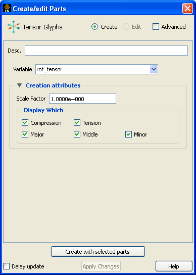
Select the tensor Variable to use.
Select which eigenvectors to display.
Click .
The glyph’s to indicate tension or compression can be modified in several ways. Put the Tensor Glyph Feature Panel into Advanced mode to open the Tensor Display.
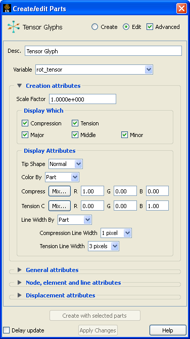
Select the desired tip shape from the Tip Shape pulldown.
Table 4: Tip Shape Choices
None No tip (default) 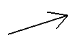
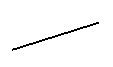
Normal Single wedge. Good for 2D problems. Plane of the wedge is based on the relative magnitudes of the components.
Triangles Two intersecting triangles. Good for 2D/3D problems
The glyph can either be colored by the part color, or show a specified color for compressions and tension.
The glyph can either be shown with the line width attribute of the glyph, or show a different line width for tension and compression.
Tensor glyphs can be animated by animating the parent part (for example, a clip plane) over space or time using flipbook or keyframe animation. See Create a Flipbook Animation or Create a Keyframe Animation for more information.
Unlike most part creation operators, tensor glyphs are created from the client's representation of the part, not the server's. For example, if you have a clip plane that is displayed using a feature angle or border representation, only those elements comprising the reduced display will yield tensor glyphs, even though all elements of the clip plane reside on the server. See Change the Visual Representation for more information.