


Select the parent part in the Part list.
In the main menu, → .
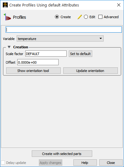
Name the new part under Desc..
Select the Variable to use.
Select an appropriate Scale Factor (or leave as Default).
If desired, enter an Offset value.
The Offset allows you to shift the profile away from the parent, but does not affect the shape.
If desired, adjust the orientation of the Plane tool using Show orientation tool or Update orientation.
The Plane Tool is used to specify the orientation and direction of the profile plot. See below for details.
Click on .
For each node of the parent part, the corresponding node on the profile curve is determined by adding the value of the Offset to the selected variable value and then multiplying the sum by the Scale Factor. The projectors of the profile are the lines that connect the nodes of the parent part to the nodes of the profile curve. The plane tool is used to specify the orientation and direction of the projectors. The projectors are created in the plane of the Plane tool by computing the cross product of the Plane tool z-axis with the 1d line segment. It is therefore a requirement that the plane tool z-axis not be co-linear with the 1d line segment. For values (after adding the Offset) that are positive, the projectors will point away from the plane tool centroid.
Although the parent part of a profile plot must be 1D, the nodes that make up the part do not have to be linear. For curved parents, the projectors of the resulting profile plot are still parallel, but they do not all lie in the same plane.