


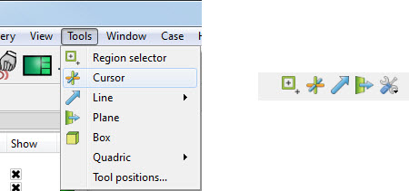
In many cases, the Line tool will automatically turn on when performing some function that requires it. You can also turn the tool on and off manually by toggling the Line entry in the Tools menu or by clicking the Line toggle on the Tools Icon Bar.
The Line tool can be placed or manipulated in three ways: interactively through direct manipulation of tool hotpoints with the mouse, by positioning the mouse pointer over a part and typing P, or precisely positioned by typing coordinates into a dialog and/or rotating the tool about its axis. With surface normal options the line remains normal.
To move the Line with the mouse:
Place the mouse pointer over the center of the tool.
Click (and hold) the left mouse button.
Drag the Line to the desired location.
Release the mouse button.
To stretch the Line with the mouse:
Place the mouse pointer over one of the Line endpoints.
Click (and hold) the left mouse button.
Drag the endpoint to the desired location.
Release the mouse button.
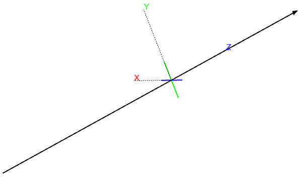
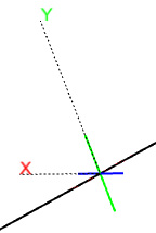
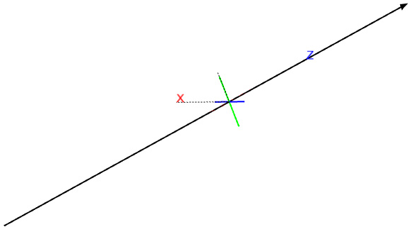
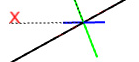
To rotate the line with the mouse:
Place the mouse over the end of one of the tool axes.
Click (and hold) the left mouse button.
Drag the axis endpoint until the line has rotated as desired.
Release the mouse button.
Note: Selecting the X axis endpoint will rotate about the Y axis, selecting the Y axis endpoint will rotate about the X axis, and selecting the Z axis endpoint will rotate in a general fashion about the centerpoint.
The mouse pointer will change when it is over a hotpoint. (/ button can be used to undo/redo the tool transformation)
Line moving and stretching is restricted to the plane perpendicular to your line of sight. If you need to move the Line in another plane, rotate the model such that the desired translation plane is perpendicular to your new line of sight.
Note: The Line will not exactly track the location of the mouse pointer.
To position the Line on a part with P:
Click the button on the Tools icon Bar.
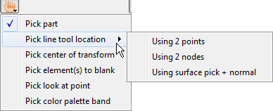
Select from the pop-up menu. (Then pick either by or .)
In the Graphics Window, place the mouse pointer on a part over the desired location for the first Line endpoint and press the P key (or whatever mouse button you have set for the Selected Pick Action in → → ). The middle mouse button is usually defaulted to perform the pick action as well.
Move the mouse pointer to the desired location for the second Line endpoint and again press the P or middle mouse key/button.
When the endpoints will be place at the pick location.
When , the endpoints will be placed at the nearest node and the ids of those nodes will be saved, such that the line tool will continue to be attached to these nodes - even if they move.
To set the Line by specifying coordinates:
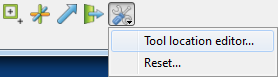
Open the Transformation Editor dialog by clicking from the Tool Locations settings icon.
If the Transformation Editor is not set to , set it by → .
Enter the desired coordinates for the endpoints into the X, Y, and Z fields and press Return.
Alternatively, you can enter the node ids for two nodes in the model. This has the effect of keeping the line tool tied to the two nodes - even if they move over time.
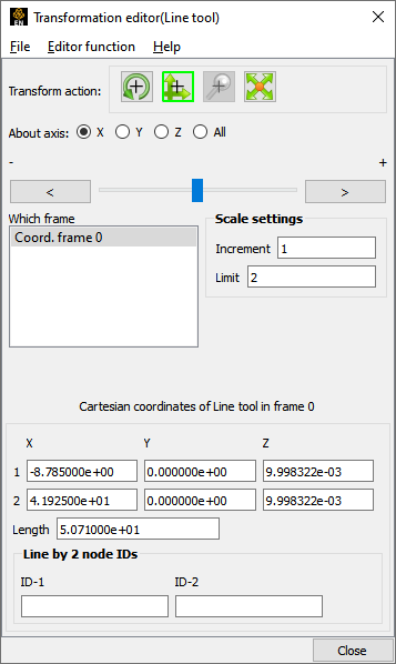
Note: The Length field is discussed in Advanced Usage below.
Rotation, translation or scaling of the tool can also be accomplished by selecting the appropriate transform action icon and the desired axis, and then manipulating the slider. In this case, the values in the Scale Settings section control the sensitivity and limit of the slider action.
Note: You can also use this dialog to view (rather than set) the position of the Line since the X,Y,Z numeric values always update to reflect the current location. If you are positioning the Line interactively with the mouse, the values will update when the mouse button is released.
Right-click a part in the graphics window and choose Place Tool, and then choose to place the line tool normal to a surface, or tangential to a surface at the location of the mouse pointer.
Right-click center selection point of the line tool (while Part Quick Action icons are available indicating that parts can be edited). You can do quick x or y rotates, hide the tool, or open the transformation editor. You can also use this right-click to quickly create a line clip, query a variable, or do a particle streamline trace with the line tool as the emitter.