


When extracting the domain parts, whether iblanked or not, some (but definitely not all combinations) of the options include:
Extracting a complete zone at original resolution,
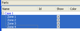
Right click on the desired zone, and click .
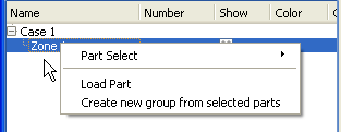
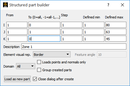
Optionally you can change the iblank domain, choose the element representation, and provide a part description.
Hit the button.
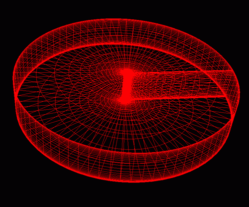
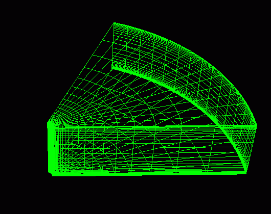
The part will be created and shown in the graphics window. In the example below, it is shown in border representation mode.
Right click on the desired zone, and click .
Optionally you can change the iblank domain, choose the element representation, and provide a part description.
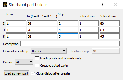
Modify the Step values.
These should be positive integer values. A step of two means to deal with every other plane, a step of four means every fourth plane, etc.
Hit the button.
The part will be created and shown in the graphics window. In the example below, it is shown in border representation mode.
Right click on the desired zone, and click .
Optionally you can change the iblank domain, choose the element representation, and provide a part description.
Modify the From and To values.
These can be anything between the ranges shown in the Min and Max columns. By default they will be the entire range, but you can modify them.
Hit the button.
The part will be created and shown in the graphics window. In the example below, it is shown in border representation mode.
Note: You now get a portion instead of the whole. Also keep in mind that we have original resolution because we set step values back to one. The step values can be other than one, and your portion will be at the coarser resolution.
Select the structured zones desired.
Optionally you can change the domain.
Modify the From and To values.
These can be anything between the ranges shown in the Min and Max columns (which will now be the min and max of all parts selected). By default the From and To will be the entire range, but you can modify them. Additionally, “-1” is a valid entry, indicating the last plane. Minus numbers are ways to specify the plane from the max back toward the min, therefore -2 equals the next to last plane.
Note: Zero is treated the same as -1.
.
Hit the button.
In this example, 4 parts will be created, and they will each be the full extent IK plane at J = 1 for each of the four zones.
Note: The IK ranges can actually vary per part because the max is specified, but each zone may be less than the max.
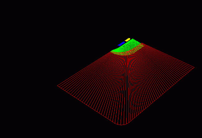
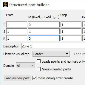
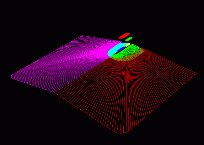
In our example, we then changed From and To to be “0”, thus extracting the last plane in each zone.
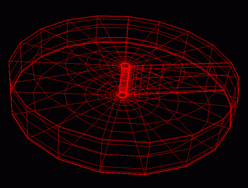
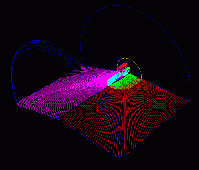
Note: Pay close attention to the image below. The second image includes complete zones that were extracted, but shown in feature angle representation so you get the feel of the complete zone.
Note: Prior to EnSight10, one could also extract multiple planes within the same zone while loading the part, through the use of a delta column. This has been discontinued, but the same effect can be achieved by using the delta field within an ijk clip.