


Results Variables
Several variables are available for you to monitor or display results. The list of commonly used monitors or results variables is based on the physics used in your simulation.
The following tables list the variables per physics type.
Generic Variables
| Mass | The volume of each simulated body multiplied by their respective densities due to the assigned material. |
| Volume | The amount of space that the bodies in the simulation occupy. |
| Mesh Statistics | The number of elements and nodes in the generated mesh. This option is only available in the Refine stage. See Monitoring Mesh Statistics for more information. |
| Mesh Quality | Diagnostic information pertaining to the quality of the generated mesh. This option is only available in the Refine stage. See Monitoring Mesh Quality for more information. |
Structural Variables
| Displacement | These are physical deformations that are calculated on and inside a model. Fixed supports prevent deformation; locations without a fixed support usually experience deformation relative to the original location. Deformations are calculated relative to the specified coordinate system. |
| Von Mises Stress | The first, second and third Von Mises stress (also known as equivalent stress) for the assessment of yield in ductile materials, such as metals. |
| Stress | A general three-dimensional stress state is calculated in terms of three normal (X, Y, Z) and three shear (XY, YZ, XZ) stress components aligned to the specified coordinate system. |
| Principal Stress |
From elasticity theory, an infinitesimal volume of material at an arbitrary point on or inside the solid body can be rotated such that only normal stresses remain and all shear stresses are zero. The three normal stresses that remain are called the principal stresses. The principal stresses are always ordered such that σ1>σ2> σ3. The principal stresses and maximum shear stress are called invariants, meaning their value does not depend on the orientation of the part or assembly with respect to its specified coordinate system. |
| Strain (elastic) | A general three-dimensional strain state is calculated in terms of three normal (X, Y, Z) and three shear (XY, YZ, XZ) strain components aligned to the specified coordinate system. |
| Principal Strain (elastic) |
From elasticity theory, an infinitesimal volume of material at an arbitrary point on or inside the solid body can be rotated such that only normal strains remain and all shear strains are zero. The three normal strains that remain are called the principal strains. The principal strains are always ordered such that ε1>ε2> ε3. The principal strains and maximum shear strain are called invariants, meaning their value does not depend on the orientation of the part or assembly with respect to its specified coordinate system. |
| Reaction Force | Reaction force is the local force reaction distribution across the constrain due to the loading. Because the distribution is local, it can vary with location on the support and are more "elemental" forces of how the surface behaves. 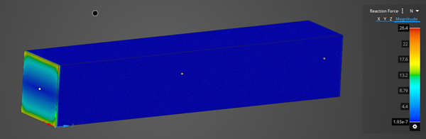 |
| Reaction Resultant | The reaction resultant is reaction load over a constraint, so the resultant forces balance out the forces applied. For example, if a cantilever beam has a force of 1000N, the resultant magnitude in Refine will also be 1000N on the entire support surface. In Explore, the resultant magnitude will be 1000N distributed between the applied surfaces. 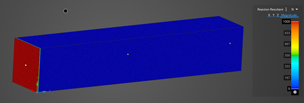 |
| Contact Reaction | The reaction forces on the contact. |
| Contact Stress |
Defined in terms of either pressure measured normal to the surfaces in contact, or frictional stress measured parallel to the surfaces in contact. For Bonded contacts, the frictional stress is shear stress at the contact location. Frictional stress is only available in the Refine stage. |
| Connection Factor of Safety |
For Contacts and Contact Groups: Factor of safety (FOS) is defined by a shear or tensile stress service limit of the bond on a contact or contact group. The shear or tensile limit value is divided by the average contact pressure stress or average contact frictional stress to obtain the factor of safety. Peeling, twisting, or other combined effects are ignored, so this should be used only as guidance. For Bolts (Refine stage only): FOS is based on the AISC WSD approach for bolt bearing (no slip), Section J3:
This is an indication for the bolt strength only and should be used as a guide. Bolt pull through, plate failure, bolt grouping effects, etc. are all ignored, and will need to be assessed separately. |
| Joint Total Force | The action of the reference body on the moving body. |
| Joint Total Moment | The action of the reference body on the moving body. |
| Bolt Axial Stress |
The stress component due to the axial load encountered in a bolt. |
| Bolt Shear Force |
The force perpendicular to the bolt axis. |
| Bolt Torsional Moment |
The moment about the bolt axis. |
| Modal Frequency | The undamped natural frequency response of a structure. Mode monitors are created automatically based on the number of modes being simulated. |
| Factor of Safety | The ratio of alternating stress at design life to the equivalent alternating stress at a given point. |
Fluid Variables
| Static Pressure | The fluid gauge pressure. |
| Total Pressure | The gauge pressure obtained by bringing the fluid isentropically to rest, sometimes referred to as stagnation pressure. |
| Velocity | The fluid velocity field. |
| Vortices Lambda 2 | A vortex core line detection method used to identify vortices from a three-dimensional fluid velocity field. A point in the velocity field is part of a vortex core only if at least two of its three eigenvalues (ordered as λ₁ ⩾ λ₂ ⩾ λ₃) are negative, that is, if λ₂ < 0. |
| Fan pressure rise | The fan pressure rise is calculated from the fan curve based on the computed volumetric flow. Combined with the volumetric flow, it represents the fan operating point where the fan is in stable equilibrium with the system. |
| Force | The static pressure is used to determine the force of the fluid on the surface (including viscous contributions). |
| Mach Number | The ratio of velocity and speed of sound. Available for compressible flows on selected bodies. |
| Density | The mass per unit volume of the fluid. |
| Volume Flow | The rate at which fluid flows through the specified flow inlet or outlet, measured by volume. |
| Mass Flow | The rate at which fluid flows through the specified flow inlet or outlet, measured by mass. |
| Pressure Drop | The difference in average total pressure measured at the inlets compared with the outlets. |
| Flow Uniformity | The uniformity index represents how a specified field variable varies over a surface, where a value of 1 indicates the highest uniformity. You can select Velocity or Temperature. |
| Radiative Heat Flux | The radiative heat flux is the flow of energy due to radiation per unit time per unit area. |
Thermal Variables
| Temperature | The temperature distribution throughout the structure or fluid. This result is available when applied to geometry or loads and constraints. |
| Heat Flux |
The flow of energy per unit time per unit area. Note:
|
| Heat Flow |
The flow of heat into the fluid region. Heat Flow can be evaluated on walls, inlets and outlets. The value is relative to a reference temperature of 25C, therefore, it is possible to see negative values on inlets and positive values on outlets. |
Electromagnetics Variables
| Peak gain |
Gain is four pi times the ratio of an antenna's radiation intensity in a given direction to the total power accepted by the antenna. It is the maximum value of gain and is unitless. |
| Peak directivity |
Directivity is defined as the ratio of an antenna's radiation intensity in a given direction to the radiation intensity averaged over all directions. It is the maximum value of directivity and is unitless. |
| Peak radiant intensity |
Peak radiant intensity is defined as the maximum radiant intensity. It is measured in Watts/Steradian. |
| Front back ratio |
Front back ratio is defined as the ratio of radiant intensity to antipode radiant intensity in the direction of peak radiant intensity. It is unitless. The direction of peak radiant intensity is the center of the main lobe. |
| Efficiency total |
Efficiency total is defined as the ratio of radiated power to incident power. It is unitless. |
| Efficiency radiated |
Efficiency radiated is defined as the ratio of radiated power to accepted power. It is unitless. |