Creating the CAD Geometry
-
Click Complete to convert the model to CAD
geometry.
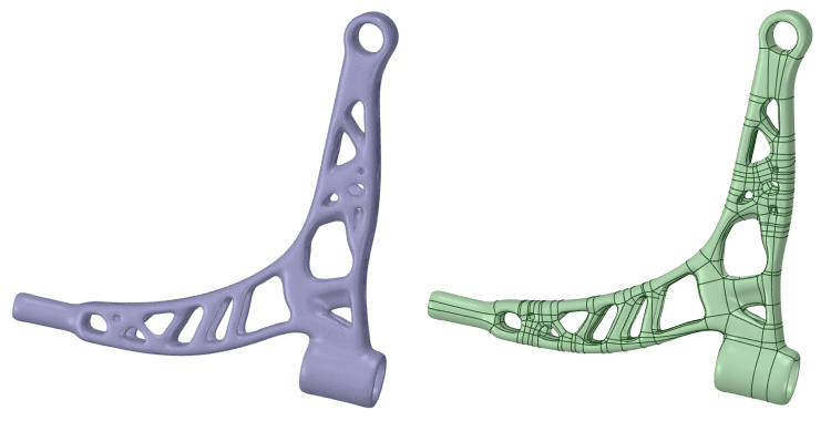
This example shows the conversion of a faceted model to CAD geometry.
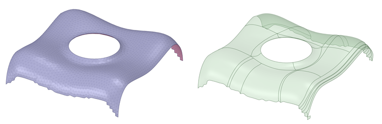
 This example shows the conversion of a faceted model with an open body to CAD geometry.
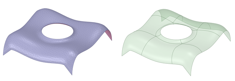 This example shows a model with a facet region.
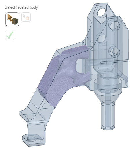 Select the faceted mesh and the solid bodies which have faces that match the facet regions as shown in the example.
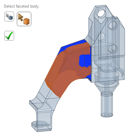 The CAD faces will be trimmed to the facet regions. Triangles on the mesh which do not match a selected CAD face will be autoskinned.In the example below, the green faces are the faces generated by the autoskin algorithm. The beige/white ones are copies from the selected CAD faces. These faces are trimmed if the facet region corresponding to a CAD face does not cover the whole face (as seen in the example).
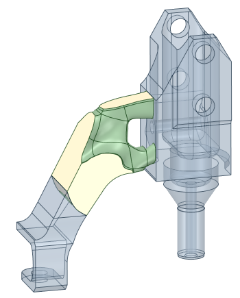
- Verify the CAD geometry. In the example, the CAD geometry created has missing
patches.
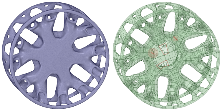 If the geometry has missing patches, use the Skin Surface tool to create the missing patches.If the boundary is not smooth, the CAD geometry creation may fail or result in incorrect geometry.