CFD can be used to determine the performance of a component at the design stage, or it can be used to analyze difficulties with an existing component and lead to its improved design.
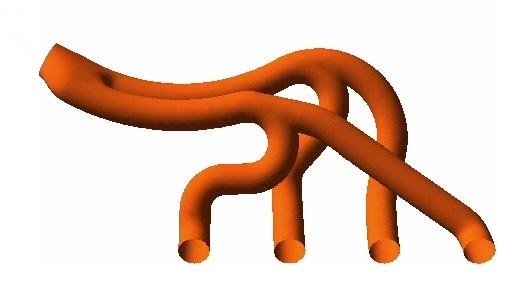
For example, the pressure drop through a component may be considered excessive:

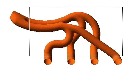
The first step is to identify the region of interest:

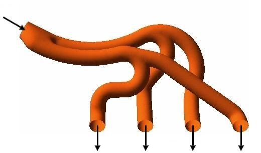
The geometry of the region of interest is then defined. If the geometry already exists in CAD, it can be imported directly. The mesh is then created. After importing the mesh into the preprocessor, other elements of the simulation including the boundary conditions (inlets, outlets, and so on) and fluid properties are defined.

The flow solver is run to produce a file of results that contains the variation of velocity, pressure and any other variables throughout the region of interest.
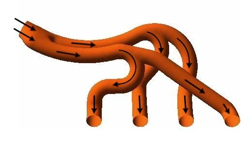
The results can be visualized and can provide the engineer an understanding of the behavior of the fluid throughout the region of interest.

This can lead to design modifications that can be tested by changing the geometry of the CFD model and seeing the effect.
The process of performing a single CFD simulation is split into four components:


