


VM228
VM228
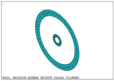
Radiation Between Infinite Coaxial Cylinders
Overview
| Reference: | R. Siegel, J. R. Howell, Thermal Radiation Heat Transfer. 3d ed. Hemisphere Publishing, 1992, p. 204–205, and 240. |
| Analysis Type(s): | Steady State Radiosity |
| Element Type(s): | |
| Input Listing: | vm228.dat |
|
VM228 requires a supplemental .cdb input file which is too long to include full input listings. This file must be downloaded and placed in your working directory for the test case to run properly. Additionally, the geometry and mesh should be regenerated. Download link: MAPDL Test Case Files for 2024 R2 vm228-1.cdb, vm228-1.iges vm228-2.cdb, vm228-2.iges |
Test Case
Two concentric infinite cylinders are transferring heat to each other through radiation. The problem is modeled as a 2D pair of concentric circles. The facing surfaces are given surface emissivity values, the non facing surfaces are at fixed temperatures.
Analysis Assumptions and Modeling Notes
The cylinders are assumed to be infinite length, with no end effects, and with uniform surface characteristics. As such, any point on one surface should have the same view factor and characteristics as any other point on the same surface.
| F(11) = 0 As a circle, it cannot see itself from any part of its surface. |
| F(12) = 1 Consequence of no radiation to space |
| F(21) = (A1/A2)F(12) Basic rule of view factors |
| F(21) = (r1/r2)F(12) |
| F(21) = r1/r2 |
| F(22) = 1 - (r1/r2) Consequence of no radiation to space |
As a check on the system, the heat flux at two points are compared to that expected by σ(T14 - T24)
A second solution of the test case is performed using radiosity surface elements. These elements are applied to all surfaces which have loads with the RDSF flag. The total number of radiation elements is reduced using the RDEC command.
Results Comparison
| Target | Mechanical APDL | Ratio | |
|---|---|---|---|
| PLANE35 | |||
| F(11) | 0.000 | 0.000 | 0.00 |
| F(21) | 0.250 | 0.249 | 1.00 |
| F(22) | 0.750 | 0.751 | 1.00 |
| Heat flux (interior) at node(0,-1,0) | 11.537 | 11.035 | 0.96 |
| Heat flux (exterior) at node(0,-4,0) | 2.884 | 2.742 | 0.95 |
| PLANE35 and SURF251 | |||
| F(11) | 0.000 | 0.000 | 0.00 |
| F(21) | 0.250 | 0.249 | 1.00 |
| F(22) | 0.750 | 0.751 | 1.00 |
| Heat flux (interior) at node(0,-1,0) | 11.537 | 11.035 | 0.96 |
| Heat flux (exterior) at node(0,-4,0) | 2.884 | 2.747 | 0.95 |