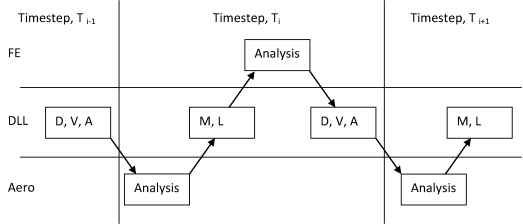
The whole offshore wind turbine structure is split into two parts. The upper part is the rotor-nacelle-assembly of the turbine including the tower and this is modeled by a wind turbine aeroelastic code.[1] The lower part is the support structure and this is modeled by structural FE as usual.
In this coupling approach, both the aeroelastic and FE code runs concurrently, with data exchange between the two programs occurring at every time step. The turbine effect as modeled by the aeroelastic code is taken into account in the FE code as a special element, which accepts the wind turbine system matrices (stiffness, damping and mass) and aerodynamic load vector as if it is a superelement.

In the diagram above, the following data items are exchanged:
D, V, A: Displacements, Velocities, Acceleration information at interface point.
M, L: Matricies (Stiffness, Damping and Mass), and/or Load Vectors.
At the beginning of a time step, the aeroelastic code is called to compute the turbine matrices and loading based on the kinematics at the end of the previous step. It is assumed that the turbine data will remain constant during the time step. After transferring the information to the FE code, the full system of equations of motion is solved by the FE code to obtain an updated solution. Finally, the turbine kinematics are passed back to the aeroelastic code to continue the time advancement process.
Further details about the theory of the fully coupled solution can be obtained from the work of Kaufer [1] and Seidal [2].
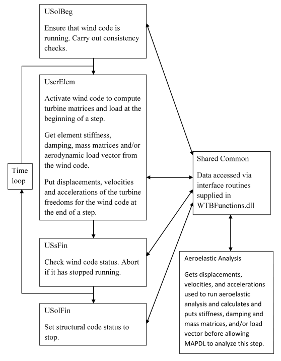
Flowchart of Wind Coupling Calculations


