Let's review a distortion compensation example. An aluminum alloy thin foil part is shown below with a layered tetrahedrons mesh of 1 mm Layer Height. We suspect that during the build the part will deform by pulling inward at the curves such that the foil will straighten. Our concern is that it will deform out of acceptable tolerances.
We set up a simple isotropic LPBF inherent strain simulation with a Strain Scaling Factor of 5. Just before solving, we added the Distortion Compensation object and set our convergence criteria as Average Deviation and Maximum Deviation = 0.1 mm and Maximum Iterations = 10.
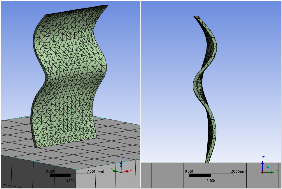
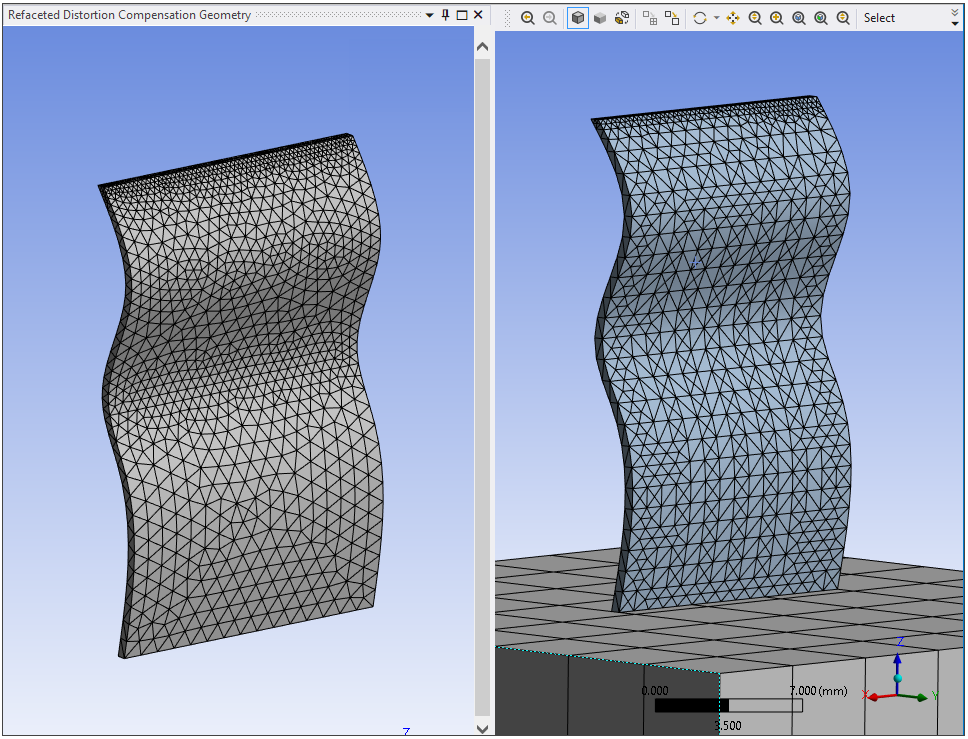
We set refaceting settings so that the target faceted mesh closely approximates the actual geometry, particularly around the curves. The image below shows the refaceted geometry on the left compared to the layered tetrahedral mesh on the right. (From the Distortion Compensation ribbon, click Show Refaceted Geometry of Parts.)
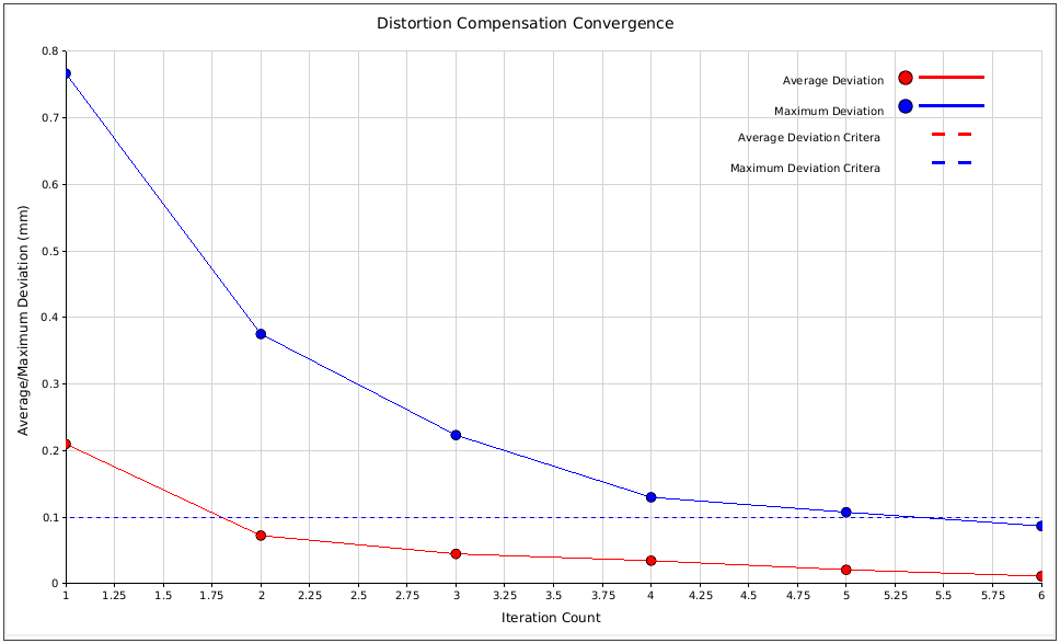
The distortion compensation converged in the sixth iteration. Here is the convergence history chart:
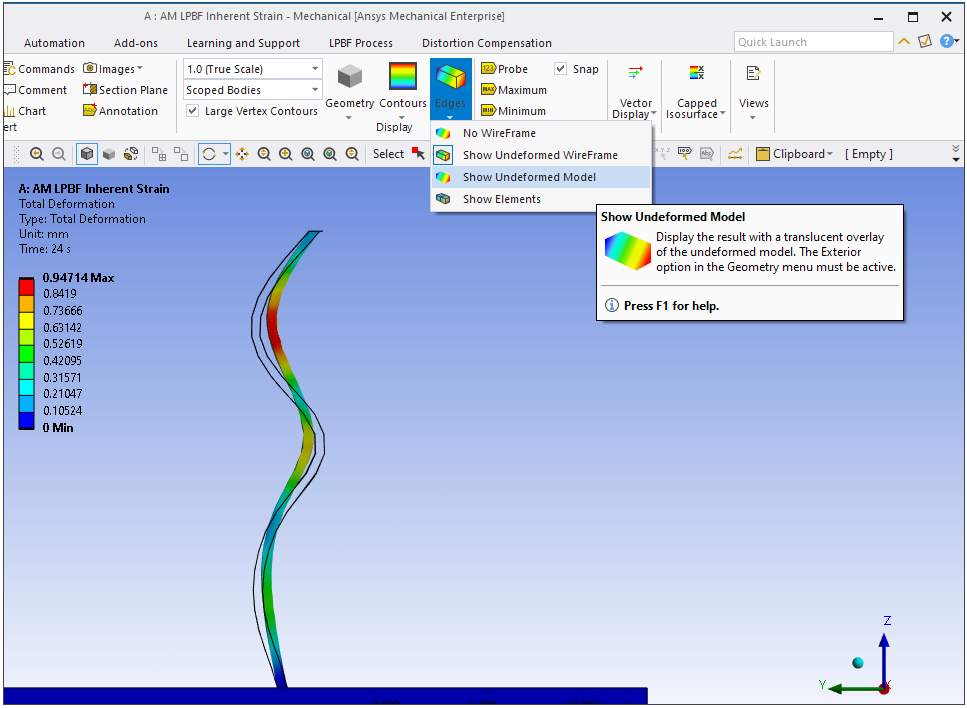
As we suspected, the strain causes the foil to pull inward at the curves resulting in a straightening effect, as shown by the animation of total deformation. The following is an animated GIF. Refresh the page to see the animation. View online if you are reading the PDF version of the help.
The automatic compensation process adjusted the geometry to compensate for the deformation. We can see the compensated geometry (resulting from iteration 5 and used as the starting point for iteration 6) by clicking Result tab, Edges, Show Undeformed Wireframe.
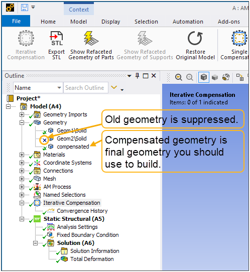
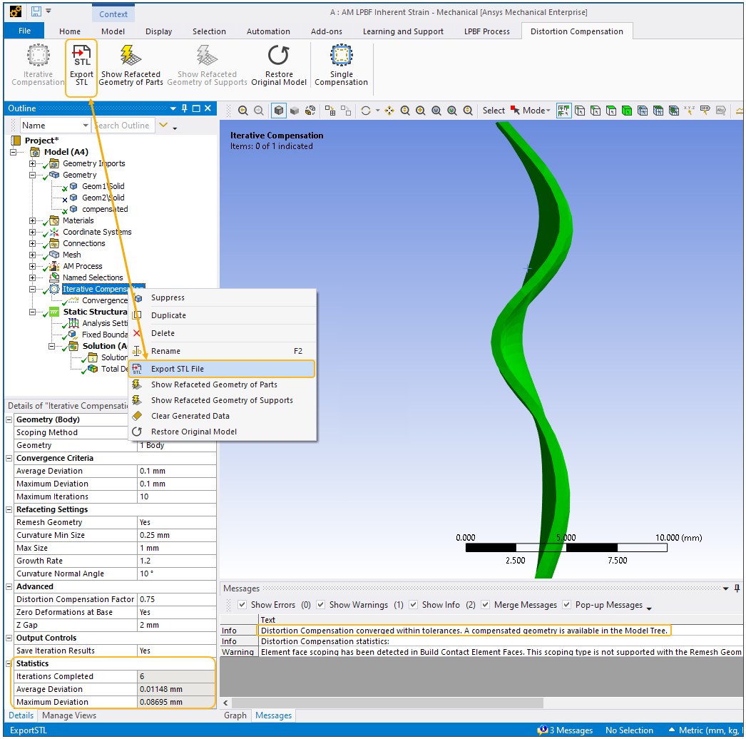
We can save the compensated geometry either by using the ribbon button or right-clicking Distortion Compensation and choosing Export STL File. This is the geometry file that we will use when we build the part.