


In the Build Settings step of our workflow, we have already accounted for convection between the build and the gas in the chamber and convection between the build and the unmelted powder around the part—in both the Build Step and the Cooldown Step. There is one other area of heat transfer to consider and that is associated with the base plate.
During the build process, the plate is typically heated on the bottom to maintain a constant, slightly elevated temperature. You may insert a temperature constraint or convection surface to simulate this during the build step. If the plate is not heated, perhaps apply a room condition convection surface, or set the surface boundary condition to adiabatic.
After the print process is complete, the base plate heating is removed and the built part cools to room temperature. This is simulated by a room-temperature convection surface applied to the bottom of the base plate in the cooldown step.
The time duration of the cooldown step is estimated based on the average part temperature at the end of the build, its volume, and material properties. Using the convection values and room temperature, the Mechanical application solves the simple heat transfer equation to get an estimate of the cool down time. It is only an estimate so you can extend it if required or put in a preferred time in analysis settings. One final step is performed to force all the temperatures to room temperature for the subsequent distortion and stress calculation.
Procedural Steps
To apply a temperature to the bottom surface of the base plate for the build step:
Right-click the Transient Thermal object and then select Insert > Temperature.
Select the bottom surface of the base plate (geometry selection) and hit Apply in the Details view.
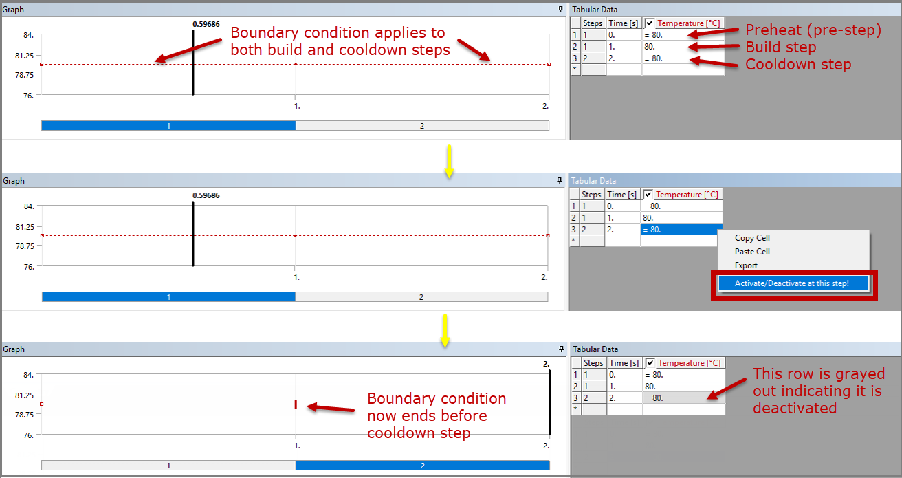
In Details under Definition, Temperature, enter a temperature value for Magnitude. (In our example we use 80°.)
In the Tabular Data area of the interface, notice the temperature value you just entered is applied for all sequence steps. (The first row of tabular data is considered T=0, the preheat condition.) In the printing process, since the heat is removed after the part is printed, you'll need to remove the temperature boundary condition for the cooldown step of the simulation. Right-click in the third row and click Activate/Deactivate at this step! which will deactivate (remove) the elevated temperature for the cooldown step.
To apply room-temperature convection to the bottom surface of the base plate for the cooldown step:
Right-click the Transient Thermal object and then select Insert > Convection.
Select the bottom surface of the base plate (geometry selection) and hit Apply in the Details view.
In Details under Definition, Film Coefficient, enter a value for the convection coefficient.
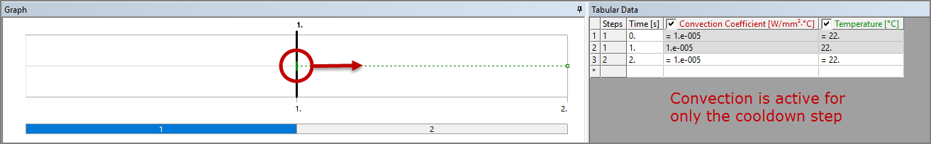
Under Ambient Temperature, enter a value of 22°. (This may be the default.)
In the Tabular Data area of the interface, select the first two rows, right-click and select Activate/Deactivate at this step! which will deactivate (remove) the convection for the build step.
It is important to use separate load objects for each change in thermal boundary conditions, as was done in the example above where temperature and convection boundary conditions were inserted separately. You may be tempted to combine them into one temperature object and specify 80° for the first two rows/steps and 22° for the last row/step, but doing so is incorrect and will cause problems.
Important: For thermal loads in AM analyses, variation in tabular values within a single load object may cause incorrect temperature profiles during the build stage. Use a separate load object to define each change in thermal boundary conditions.