


You can use the MechanicalCameraWrapper to manipulate the camera for precise control of model visualization.
To access this API, you enter these commands in the console:
camera = Graphics.Camera
camera
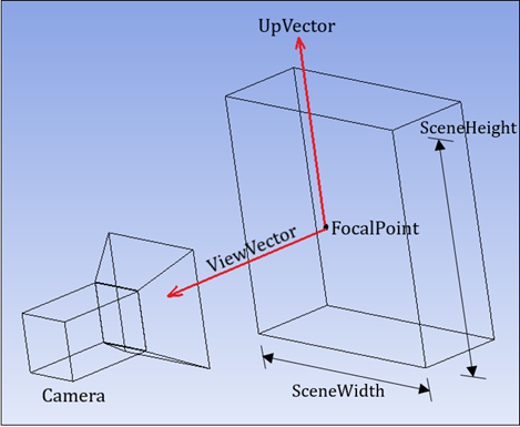
The following properties together represent the state of the camera view:
| Property | Description |
|---|---|
FocalPoint | Gets or sets the focal point of the camera. Coordinates are in the global coordinate system. |
SceneHeight | Gets or sets the scene height (in length units) that will be projected and fit to the viewport. |
SceneWidth | Gets or sets the scene width (in length units) that will be projected and fit to the viewport. |
UpVector | Gets or sets the vector pointing up from the focal point. |
ViewVector | Gets or sets the vector pointing from the focal point to the camera. |
An example follows for using these properties to change the camera state:
camera.FocalPoint = Point((0.0,0.0,0.0), "mm")
camera.ViewVector = Vector3D(1.0,0.0,0.0)
camera.UpVector = Vector3D(0.0,1.0,0.0)
camera.SceneHeight = Quantity(100, “mm”)
camera.SceneWidth = Quantity(150, “mm”)
In addition to changing one or more specific properties, user-friendly methods are available for manipulating the camera state.
To fit the view to the whole model or selection:
camera.SetFit(ISelectionInfo selection = null)
To rotate along a particular axis (global or screen):
camera.Rotate(double angle, CameraAxisType axisType)
To set a specific view orientation:
camera.SetSpecificViewOrientation(ViewOrientationType orientationType)
Two examples follow.
Example 1
This code rotates the model by 30 degrees about the direction normal to the current screen display:
camera.Rotate(30, CameraAxisType.ScreenZ)
Example 2
These code samples fit the view to a selection (either a face with a known ID or a named selection).
#fit view to face #28
selection = ExtAPI.SelectionManager.CreateSelectionInfo(SelectionTypeEnum.GeometryEntities)
selection.Ids = [28]
camera.SetFit(selection)
#fit view to the first named selection
named_selection = Model.NamedSelections.Children[0]
camera.SetFit(named_selection)
SceneHeight and SceneWidth Usage
The two properties SceneHeight and
SceneWidth, along with the existing camera APIs (such as
FocalPoint, UpVector, and
ViewVector) determine the volume of the scene. This volume
defines the minimum view that will be visible (without any distortion) after projection
onto a 2D viewport in graphics (which may have a different aspect ratio.) These
quantities are in length units and can only be affected by zoom operations like zoom
in/out, zoom to fit, and box zoom. This means that for a graphics window of a given
aspect ratio, the extent defined by these two properties will always be seen on the
screen (sometimes with additional “padding” depending on the aspect
ratio).
An example scenario follows:
Open a model and zoom to fit. The
SceneHeightandSceneWidthare equal to the bounding box of the directed view. There is horizontal padding because the viewport boundary is larger than the bounding box in that dimension.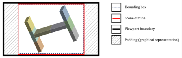
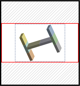
If you set
SceneHeightandSceneWidthto one-third (⅓) of their original values, the camera zooms in. The deciding factor isSceneHeightbecause of the screen’s aspect ratio and orientation. The scene, defined bySceneWidthandSceneHeight, is then scaled in or out, maintaining the aspect ratio until the height equals the viewport height.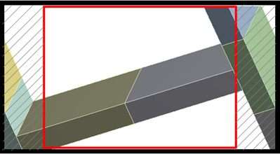
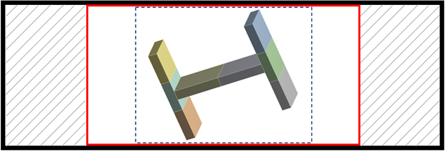
If you now resize the viewport panel to be taller and more slender, the scene defined by
SceneHeightandSceneWidthis then scaled in or out, maintaining the aspect ratio until the width equals the viewport width.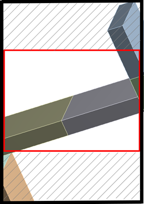
Let’s say after point 1, you increase the
SceneWidthto something beyond the model bounding box (such that it includes the padding space).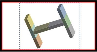
If you enlarge the viewport panel in either direction, the scene parameters still hold their shape.
UpVector Usage
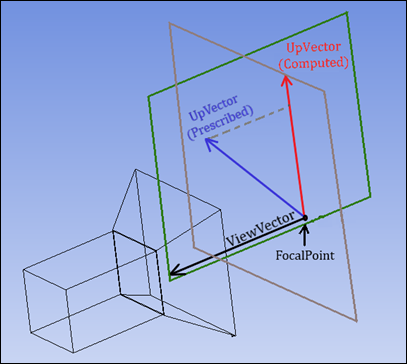
Mathematically, the UpVector and
ViewVector of the camera must be perpendicular. Together they
define the camera orientation, which in the following figure is shown by the green
half-plane. However, you can use the API to prescribe any
UpVector that is not collinear with the
ViewVector. The camera orientation’s
UpVector is then internally computed to use the projection
(dashed line) of the prescribed UpVector (blue line) onto the
brown plane perpendicular to the ViewVector (black line). The
camera still reports back the prescribed UpVector with the
UpVector property.
Note: In the half-plane, there are an infinite number of prescribed
UpVector choices that result in the same computed
UpVector.