


Goal: Print the element id and face index of all selected element faces.
Note: Elements created in Mechanical may not have the same connectivity as those in the Mechanical APDL application. Mechanical elements are converted to the necessary element type when the application creates the solver input file.
Element Shape Overview
The following descriptions show the ordering of nodes and faces for the element types generated by the Mechanical meshing component and how they are converted to APDL elements (or the closest available APDL element type).
- kAnsTetrahedra
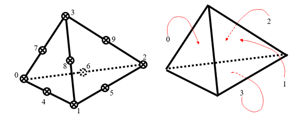
Corner nodes:
0, 1, 2, 3 Midside nodes:
4, 5, 6, 7, 8, 9 (if present) Faces and their orientations are defined by their bounding nodes:
face 0: 0, 1, 3, 4, 8, 7. face 1: 1, 2, 3, 5, 9, 8 face 2: 2, 0, 3, 6, 7, 9 face 3: 0, 2, 1, 6, 5, 4 ANSYS Usage Note
The nodes of a kAnsTetrahedra (0…9) map directly to the nodes of an ANSYS-spec SOLID92 (i…r). However, the faces do not directly map between the two:
Standard kAnsTetrahedra vs ANSYS SOLID92 Face Ids
kAnsTetrahedra Face 0 1 2 3 SOLID92 Face 2 3 4 1 #define TET_FACE_TO_ANSYS(x) x=((x+1)%4)+1; //TODO: which is faster: 2 adds, 1 mod, 1 assignment OR
#define TET_FACE_TO_ANSYS(x) x+=3==x?-2:2; // 1 add, 1 compare, 1 assignment
#define TET_FACE_FROM_ANSYS(x) x=(x+2)%4;
- kAnsHexahedra
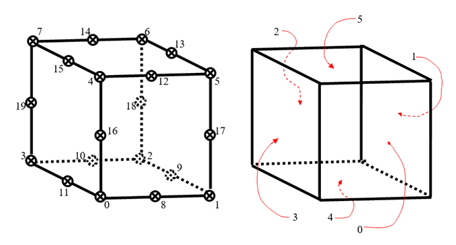
Corner nodes:
0, 1, 2, 3, 4, 5, 6, 7 Midside nodes:
8, 9, 10, 11, 12, 13, 14, 15, 16, 17, 18, 19 (if present) Faces and their orientations are defined by their bounding nodes:
face 0: 0, 1, 5, 4, 8, 17, 12, 16 face 1: 1, 2, 6, 5, 9, 18, 13, 17 face 2: 2, 3, 7, 6, 10, 19, 14, 18 face 3: 3, 0, 4, 7, 11, 16, 15, 19 face 4: 0, 3, 2, 1, 11, 10, 9, 8 face 5: 4, 5, 6, 7, 12, 13, 14, 15 ANSYS Usage Note
The nodes of a kAnsHexahedra (0…19) map directly to the nodes of an ANSYS-spec SOLID95 (i…b). However, the faces do not directly map between the two:
Standard kAnsHexahedra vs ANSYS SOLID45/95 Face Ids
kAnsHexahedra Face 0 1 2 3 4 5 SOLID95 Face 2 3 4 5 1 6 #define HEX_FACE_TO_ANSYS(x) x+=4>x?2:4==x?3:-1;
#define HEX_FACE_FROM_ANSYS(x) x-=6==x?1:1==x?-3:2;
- kAnsWedge
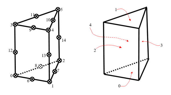
Corner nodes:
0, 1, 2, 3, 4, 5 Midside nodes:
6, 7, 8, 9, 10, 11, 12, 13, 14 (if present) Faces and their orientations are defined by their bounding nodes:
face 0: 0, 2, 1, 8, 7, 6 face 1: 3, 4, 5, 9, 10, 11 face 2: 0, 1, 4, 3, 6, 13, 9, 12 face 3: 1, 2, 5, 4, 7, 14, 10, 13 face 4: 0, 3, 5, 2, 12, 11, 14, 8 ANSYS Usage Note
The nodes of a kAnsWedge (0…14) map directly to the nodes of a degenerate ANSYS-spec SOLID95 (i…b). However, the faces do not directly map between the two.
Standard kAnsWedge vs ANSYS SOILD45/95 Node Ids
kAnsWedge 0 1 2 3 4 5 6 7 8 9 10 11 12 13 14 SOLID95 i j k, l, s m n o, p, w q r t u v x y z a, b Standard kAnsWedge vs ANSYS SOLID45/95 Face Ids
kAnsWedge Face 0 1 2 3 4 SOLID95 Face 1 6 2 3 4, 5 #define WEDGE_FACE_TO_ANSYS(x) if(2>x)x=x?6:1;
#define WEDGE_FACE_FROM_ANSYS(x) if(1==x||5==x)x-=1; else if(6==x)x=1;
- kAnsPyramid
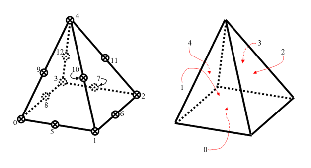
Corner nodes:
0, 1, 2, 3, 4 Midside nodes:
5, 6, 7, 8, 9, 10, 11, 12 (if present) Faces and their orientations are defined by their bounding nodes:
face 0: 0, 3, 2, 1, 8, 7, 6, 5 face 1: 0, 1, 4, 5, 10, 9 face 2: 1, 2, 4, 6, 11, 10 face 3: 3, 4, 2, 12, 11, 7 face 4: 0, 4, 3, 9, 12, 8 ANSYS Usage Note
The nodes of a kAnsPyramid (0…12) map directly to the nodes of a degenerate ANSYS-spec SOLID95 (i…b). Likewise, the facesof the kAnsPyramid map directly to the faces of the degenerate SOLID95.
Standard kAnsPyramid vs ANSYS SOILD45/95 Node Ids
kAnsWedge 0 1 2 3 4 5 6 7 8 9 10 11 12 SOLID95 l j k l m, n, o, p, u, v, w, x q r s t y z a b Standard kAnsPyramid vs ANSYS SOLID45/95 Face Ids
kAnsPyramid Face 0 1 2 3 4 SOLID95 Face 1 2 3 4 5 #define PYRAMID_FACE_TO_ANSYS(x) x+=1;
#define PYRAMID_FACE_FROM_ANSYS(x) x-=6>x?1:7; // set ANSYS SOLID95 face #6 to be –1 in the pyramid
- kAnsTriangle
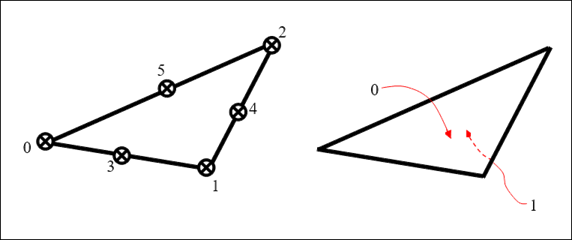
Corner nodes:
0, 1, 2 Midside nodes:
3, 4, 5 (if present) Faces and their orientations are defined by their bounding nodes:
face 0: 0, 1, 2, 3, 4, 5 face 1: 0, 2, 1, 5, 4, 3 ANSYS Usage Note
The nodes of a kAnsTriangle (0…5) map directly to the nodes of an ANSYS-spec triangle such as PLANE35(i…n). However, ANSYS-spec triangles do not have faces.
- kAnsQuadrilateral
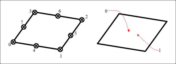
Corner nodes:
0, 1, 2, 3 Midside nodes:
4, 5, 6, 7 (if present) Faces and their orientations are defined by their bounding nodes:
face 0: 0, 1, 2, 3, 4, 5, 6, 7 face 1: 0, 3, 2, 1, 7, 6, 5, 4 ANSYS Usage Note
The nodes of a kAnsQuadrilateral (0…7) map directly to the nodes of an ANSYS-spec quadrilateral such as PLANE82(i…p). However, ANSYS-spec quadrilaterals do not have faces.
- kAnsLine
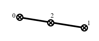
Corner nodes: 0, 1
Midside nodes: 2
- kAnsPoint

Corner nodes: 0
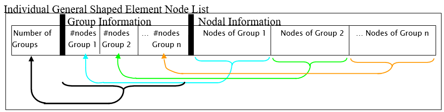
- kAnsGeneral
The kAnsGeneral shape is a special case, as it defines its own shape based on its internal groups. The first value in the nodelist of a general shaped element is the number of groups (n) in the element. Following this is n values, each representing the number of nodes in that particular group. Following this is the actual nodes themselves.
Code:
# Purpose of the script: prints selected element faces area

g_elementTypeToElemFaceNodeIndices = {
    ElementTypeEnum.kTri3 : [ [ 0, 1, 2 ] ],
    ElementTypeEnum.kTri6 : [ [ 0, 1, 2, 4, 5, 6 ] ],

    ElementTypeEnum.kQuad4 : [ [ 0, 1, 2, 4 ] ],
    ElementTypeEnum.kQuad8 : [ [ 0, 1, 2, 4, 5, 6, 7, 8 ] ],

    ElementTypeEnum.kTet4 : [ [ 0, 1, 3 ], [ 1, 2, 3 ], [ 2, 0, 3 ], [ 0, 2, 1 ] ],
    ElementTypeEnum.kTet10 : [ [ 0, 1, 3, 4, 8, 7 ], [ 1, 2, 3, 5, 9, 8 ], [ 2, 0, 3, 6, 7, 9 ], [ 0, 2, 1, 6, 5, 4 ] ],

    ElementTypeEnum.kPyramid5 : [ [ 0, 3, 2, 1 ], [ 0, 1, 4 ], [ 1, 2, 4 ], [ 3, 4, 2 ], [ 0, 4, 3 ] ],
    ElementTypeEnum.kPyramid13 : [ [ 0, 3, 2, 1, 8, 7, 6, 5 ], [ 0, 1, 4, 5, 10, 9 ], [ 1, 2, 4, 6, 11, 10 ], [ 3, 4, 2, 12, 11, 7 ], [ 0, 4, 3, 9, 12, 8 ] ],

    ElementTypeEnum.kWedge6 : [ [ 0, 2, 1 ], [ 3, 4, 5 ], [ 0, 1, 4, 3 ], [ 1, 2, 5, 4 ], [ 0, 3, 5, 2 ] ],
    ElementTypeEnum.kWedge15 : [ [ 0, 2, 1, 8, 7, 6 ], [ 3, 4, 5, 9, 10, 11 ], [ 0, 1, 4, 3, 6, 13, 9, 12 ], [ 1, 2, 5, 4, 7, 14, 10, 13 ], [ 0, 3, 5, 2, 12, 11, 14, 8 ] ],

    ElementTypeEnum.kHex8 : [ [ 0, 1, 5, 4 ], [ 1, 2, 6, 5 ], [ 2, 3, 7, 6 ], [ 3, 0, 4, 7 ], [ 0, 3, 2, 1 ], [ 4, 5, 6, 7 ] ],
    ElementTypeEnum.kHex20 : [ [ 0, 1, 5, 4, 8, 17, 12, 16 ], [ 1, 2, 6, 5, 9, 18, 13, 17 ], [ 2, 3, 7, 6, 10, 19, 14, 18 ], [ 3, 0, 4, 7, 11, 16, 15, 19 ], [ 0, 3, 2, 1, 11, 10, 9, 8 ], [ 4, 5, 6, 7, 12, 13, 14, 15 ] ]
}

def Norm(vec):
    return sqrt(vec[0]*vec[0] + vec[1]*vec[1] + vec[2]*vec[2])

def CrossProduct(a, b):
    return [ a[1]*b[2] - a[2]*b[1], a[2]*b[0] - a[0]*b[2], a[0]*b[1] - a[1]*b[0] ]

def TriangleArea(a, b, c):
    ab = [b[0]-a[0], b[1]-a[1], b[2]-a[2]]
    ac = [c[0]-a[0], c[1]-a[1], c[2]-a[2]]
    n = CrossProduct(ab, ac)
    area = 0.5 * Norm(n)
    #print("a={0}, b={1}, c={2}, ab={3}, ac={4}, n={5}, area={6}".format(a, b, c, ab, ac, n, area))
    return area

def GetElementFaceNodes(element_id, element_face_index):
    mesh = ExtAPI.DataModel.MeshDataByName("Global")
    element = mesh.ElementById(element_id)
    element_node_indices = g_elementTypeToElemFaceNodeIndices[element.Type][element_face_index]
    return [element.Nodes[element_node_index] for element_node_index in element_node_indices]

def GetElementFaceArea(element_id, element_face_index):
    element_face_nodes = GetElementFaceNodes(element_id, element_face_index)
    if len(element_face_nodes) == 3 or len(element_face_nodes) == 6:
        # it's a triangle
        return \
        TriangleArea( \
            [element_face_nodes[0].X, element_face_nodes[0].Y, element_face_nodes[0].Z], \
            [element_face_nodes[1].X, element_face_nodes[1].Y, element_face_nodes[1].Z], \
            [element_face_nodes[2].X, element_face_nodes[2].Y, element_face_nodes[2].Z])
    else:
        # it's a quadrangle (made of 2 triangles)
        return \
        TriangleArea( \
            [element_face_nodes[0].X, element_face_nodes[0].Y, element_face_nodes[0].Z], \
            [element_face_nodes[1].X, element_face_nodes[1].Y, element_face_nodes[1].Z], \
            [element_face_nodes[2].X, element_face_nodes[2].Y, element_face_nodes[2].Z]) + \
        TriangleArea( \
            [element_face_nodes[0].X, element_face_nodes[0].Y, element_face_nodes[0].Z], \
            [element_face_nodes[2].X, element_face_nodes[2].Y, element_face_nodes[2].Z], \
            [element_face_nodes[3].X, element_face_nodes[3].Y, element_face_nodes[3].Z])

def GetCurrentSelectedElementFaces():
    current_selection = ExtAPI.SelectionManager.CurrentSelection
    if current_selection.SelectionType == SelectionTypeEnum.MeshElementFaces:
        element_ids = current_selection.Ids
        element_face_indices = current_selection.ElementFaceIndices
        return (element_ids, element_face_indices)
    elif current_selection.SelectionType == SelectionTypeEnum.MeshElements:
        element_ids = current_selection.Ids
        element_face_indices = [0 for i in element_ids]
        return (element_ids, element_face_indices)
    else:
        return ([], [])

def PrintCurrentSelectedElementFacesElementFacesArea():
    (element_ids, element_face_indices) = GetCurrentSelectedElementFaces()
    if len(element_ids) < 1:
        print('No element faces selected')
        return

    text = ''
    for i in range(len(element_ids)):
        area = GetElementFaceArea(element_ids[i], element_face_indices[i])
        text += 'element id={0}, faceIndex={1}, area={2}\n'.format(element_ids[i], element_face_indices[i], area)
    print(text)

PrintCurrentSelectedElementFacesElementFacesArea()