


The supplied extension Coupling creates a tool for coupling
two sets of nodes related to two edges. This extension demonstrates how you can
develop your own preprocessing feature, such as a custom load, to address a specific
need.
The file Coupling.xml follows.
<extension version="1" name="Coupling">
<guid shortid="Coupling">e0d5c579d-0263-472a-ae0e-b3cbb9b74b6c</guid>
  <script src="main.py" />
  <interface context="Mechanical">
    <images>images</images>
    <toolbar name="Coupling" caption="Coupling">
      <entry name="Coupling" icon="support">

        <callbacks>
          <onclick>CreateCoupling</onclick>
        </callbacks>
      </entry>
    </toolbar>
  </interface>

  <simdata context="Mechanical">

		<load name="Coupling" version="1" caption="Coupling" icon="support" issupport="true"
          color="#FF0000">
			<callbacks>
				<getsolvecommands>SolveCmd</getsolvecommands>
				<onshow>ShowCoupling</onshow>
				<onhide>HideCoupling</onhide>
			</callbacks>

			<property name="Source" caption="Source" control="scoping">
				<attributes selection_filter="edge" />
				<callbacks>
					<isvalid>IsValidCoupledScoping</isvalid>
					<onvalidate>OnValidateScoping</onvalidate>
				</callbacks>
			</property>

			<property name="Target" caption="Target" control="scoping">
				<attributes selection_filter="edge" />
				<callbacks>
					<isvalid>IsValidCoupledScoping</isvalid>
					<onvalidate>OnValidateScoping</onvalidate>
				</callbacks>
			</property>

			<property name="Reverse" caption="Reverse" control="select" default="No">
				<attributes options="No,Yes" />
				<callbacks>
					<onvalidate>OnValidateReverse</onvalidate>
				</callbacks>
			</property>
		</load>
  </simdata>
</extension>
As in the earlier custom load
example, the element <interface> adds a
toolbar and a toolbar button to Mechanical. The callback function
<CreateCoupling> is invoked when the toolbar
button is clicked.
The element <simdata> encapsulates the
information that defines the support. The value for the attribute
issupport is set to true. The attribute
issupport is of particular importance because it
tells Mechanical which type of boundary condition to apply. Three result level
callback functions are declared.
The function
SolveCmdis registered and called for an event that gets fired when the solver input is being written.Both the functions
ShowCouplingandHideCouplingare registered and called for events used to synchronize tree view selections with content in the graphics pane.
The details needed to define the inputs and behavior of this special load
consist of three properties, Source,
Target, and Reverse, along
with their behavioral callbacks.
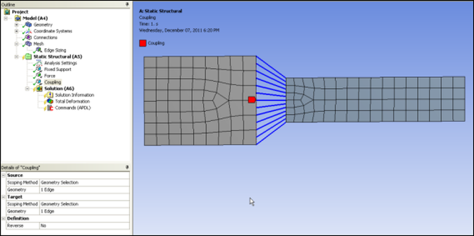
The following figure shows how a fully defined coupling appears in Mechanical.
The IronPython script main.py for this extension follows.
import graphics

def CreateCoupling(analysis):
    analysis.CreateLoadObject("Coupling")

#-------------------------------
#   Callbacks
#-------------------------------

def OnValidateReverse(load, prop):
    ShowCoupling(load)

def OnValidateScoping(load, prop):
    ShowCoupling(load)

def IsValidScoping(load, prop):

    if not prop.Controller.isvalid(load, prop):
        return False

    selection = prop.Value
    if selection == None: return False
    if selection.Ids.Count != 1: return False
    return True

def IsValidCoupledScoping(load, prop):

    sProp = load.Properties["Source"]
    tProp = load.Properties["Target"]

    if not IsValidScoping(load, sProp):
        return False
    if not IsValidScoping(load, tProp):
        return False

    sIds = sProp.Value.Ids
    tIds = tProp.Value.Ids

    try:
        mesh = load.Analysis.MeshData
        sNum = mesh.MeshRegionById(sIds[0]).NodeCount
        tNum = mesh.MeshRegionById(tIds[0]).NodeCount
        if sNum == 0 or tNum == 0: return False
    except:
        return False


    return sNum == tNum

#-------------------------------
#   Show / Hide
#-------------------------------

graphicsContext = {}
def getContext(entity):
     global graphicsContext
     if entity.Id in graphicsContext : return graphicsContext[entity.Id]
     else : return None

def setContext(entity, context):
     global graphicsContext
     graphicsContext[entity.Id] = context

def delContext(entity):
    context = getContext(entity)
    if context != None : context.Visible = False
    context = None
    setContext(entity, None)

def ShowCoupling(load):
    delContext(load)
    ctxCoupling = ExtAPI.Graphics.CreateAndOpenDraw3DContext()

    sourceColor = load.Color
    targetColor = 0x00FF00
    lineColor   = 0x0000FF

    sProp = load.Properties["Source"] ; sSel = sProp.Value
    tProp = load.Properties["Target"] ; tSel = tProp.Value

    ctxCoupling.LineWeight = 1.5
    if sSel != None:
        ctxCoupling.Color = sourceColor
        for id in sSel.Ids:
            graphics.DrawGeoEntity(ExtAPI, load.Analysis.GeoData, id, ctxCoupling)
    if tSel != None:
        ctxCoupling.Color = targetColor
        for id in tSel.Ids:
            graphics.DrawGeoEntity(ExtAPI, load.Analysis.GeoData, id, ctxCoupling)

    if IsValidSelections(load):

        ctxCoupling.Color = lineColor
        ctxCoupling.LineWeight = 1.5

        mesh = load.Analysis.MeshData
        sList, tList = GetListNodes(load)

        for sId, tId in zip(sList, tList):
            sNode = mesh.NodeById(sId)
            tNode = mesh.NodeById(tId)
            ctxCoupling.DrawPolyline([sNode.X,sNode.Y,sNode.Z,tNode.X,tNode.Y,tNode.Z])

    ctxCoupling.Close()
    ctxCoupling.Visible = True
    setContext(load, ctxCoupling)

def HideCoupling(load):
    delContext(load)

#-------------------------------
#   Commands
#-------------------------------

def SolveCmd(load, s):
    s.WriteLine("! Coupling - CP")
    sList, tList = GetListNodes(load)
    for sId, tId in zip(sList, tList):
        s.WriteLine("CP,NEXT,ALL,{0},{1}", sId, tId)

#-------------------------------
#   Utils
#-------------------------------

def IsValidSelections(load):
    return load.Properties["Source"].IsValid and load.Properties["Target"].IsValid

def GetListNodes(load):

    if IsValidSelections(load):

        sProp = load.Properties["Source"] ; sIds = sProp.Value.Ids
        tProp = load.Properties["Target"] ; tIds = tProp.Value.Ids

        geometry = ExtAPI.DataModel.GeoData
        mesh = load.Analysis.MeshData

        sList = GetSubListNodes(geometry, mesh, sIds[0])
        tList = GetSubListNodes(geometry, mesh, tIds[0])

        rev = False
        r = load.Properties["Reverse"].Value
        if r == "Yes": rev = True

        sList = sorted(sList, key=sList.get)
        tList = sorted(tList, key=tList.get, reverse=rev)

    return (sList, tList)

def GetSubListNodes(geometry, mesh, refId):

    entity = geometry.GeoEntityById(refId)
    region = mesh.MeshRegionById(refId)

    result = {}
    pt = System.Array.CreateInstance(System.Double, 3)

    for nodeId in region.NodeIds:
        node = mesh.NodeById(nodeId)
        pt[0], pt[1], pt[2] = (node.X, node.Y, node.Z)
        result[nodeId] = entity.ParamAtPoint(pt)

    return result
This script defines a callback function named
<CreateCoupling>. When activated by clicking
the Coupling toolbar button, this callback
creates the load Coupling. The callback invokes the
function CreateLoadObject for the current analysis. The
function SolveCmd is invoked when the solver input is
being generated. SolveCmd invokes
GetListNodes to obtain two lists of node IDs
corresponding to the edges Target and
Source. These node IDs are then used to write APDL CP
commands to the solver input. GetListNodes is also
invoked by the callback function <ShowCoupling>. In
<ShowCoupling>, the interface
IGraphics is used to create a graphics context. Using
the object returned, the inter-nodal lines are drawn to provide a visual
representation of the coupling.
The graphics context associated with this custom load and the validation of the user inputs provide for managing more varied situations than the earlier custom load example. This explains why this example requires more functions and sub-functions.