This section reviews the wizard interface and the processes performed in each step of
the wizard Wizard Demo.
The first step is Design, which defines the geometries.
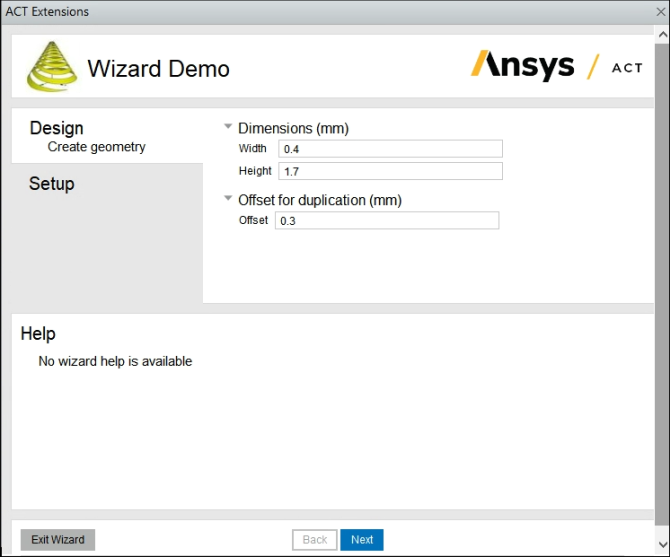
In this step:
Two property groups define the three dimension properties.
The first property group
Dimensionsincludes the propertiesWidthandHeightfor creating the first rectangle.The second property group
Offset for
                                duplication
, includes the propertyOffsetfor duplicating the first rectangle.
Two callbacks are defined:
The callback
<onupdate>invokes the functionOnUpdate1when is clicked. This function creates the new project, creates the first rectangle based on the entered dimensions, and then creates the second rectangle via duplication and offset according to the entered offset value.The callback
<onreset>is invoked when is clicked in step 2. This button is enabled only if the callback<onreset>has been defined.
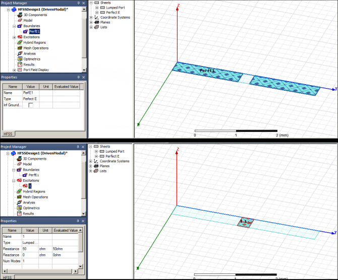
The next step is Setup, which defines and applies the boundary conditions.
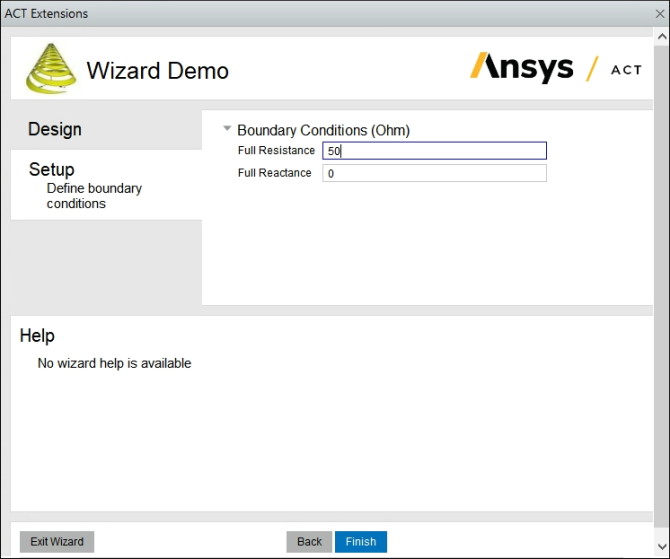
In this step:
The property group for boundary conditions defines two properties:
Full ResistanceandFull Reactance.The callback
<onupdate>invokes the functionOnUpdate2when is clicked. This function applies the boundary conditions to both rectangles.
Once the wizard has completed, the boundary conditions can be viewed in Electronics Desktop by selecting them in the Project Manager tree.