Understanding Variable Pitches Mapping
This page describes how to create variable pitches curves for a good calculation.
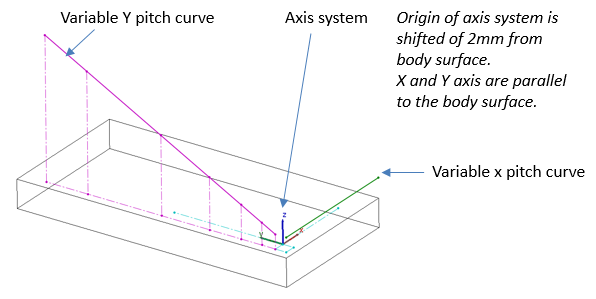
The Variable Pitch Mapping uses two curves sketched in the CAD environment (one along the X axis, one along the Y axis). These curves will be used to determine the distribution of the mapping along both axes.
Positioning and Calculation
For a correct construction of the 3D Texture, position the start point of the curve defining a variable pitch on the side of the origin of the axis system:
The 3D Texture algorithm reference is the axis system. It defines a projection direction (Z axis) used to:
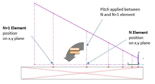
Position new element: the position is first computed in the plan, then projected on the body along projection direction.
Calculate distance between two variable pitches: the distance between two elements (N and N+1) is the distance between the curve and the position of the first element (N) in the axis plane along projection direction.