Understanding Parameters of a Poly Ellipsoidal Reflector
This page describes parameters to set when creating a Poly Ellipsoidal Reflector.
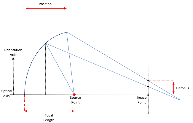
Figure 1. Side view of an angular section with parameters to set to create the reflector.
Axis System
Source point: this point defines the source position. The source is a simplified source that emits light from a single point
and position. The source is used to calculate the poly ellipsoid profiles and illuminate the reflector.
Image point: this point corresponds to the reflector's focus point, that is where the light rays converge when no defocus is
applied.
Orientation axis: the orientation axis is the line fixing the orientation of the reflector around the optical axis. The optical
axis passes through the source point and image point. The 0 degree angular section is located in the plane defined by the optical axis and the Orientation Axis.
Note: The orientation axis may not be defined on a plane normal to the optical axis.
Hole Diameter
Diameter of the hole at the bottom of the reflector. This hole is used to position the light source.
If you want to create a reflector without a hole (for example a reflector with
a LED and not a bulb as light source), deactivate this option to create a closed reflector.
Focal Length
The Focal Length is the distance between the source and the back of the Poly Ellipsoid Reflector.
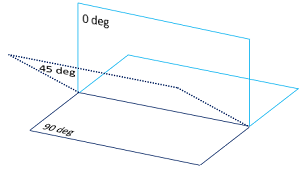
Angular Sections
The angular sections define how the reflector is built. You can create as many sections as needed between 0° and 90°.
Figure 2. 0 and 90 degree planes with one section added at 45°
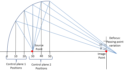
Control Planes
Creating control planes allows you to drive the overall beam spread.
Designing a poly
ellipsoidal reflector without creating any control plane and defocus would create a pure ellipsoidal reflector that would generate a spotlight beam (once passing through the projection lens).
Each control plane is identified by its Position from the back of the reflector and its Defocus
value.
The Position is expressed in mm and is defined by the distance between the back of the reflector and where you want to place
the control plane.
The Defocus can be defined for each control plane and corresponds to the distance from the image point on image point plane.
Figure 3. Control planes defined between 0 and 50mm with defocus applied.