


LiDAR Projected Grid Parameters
Three projected grid are generated as field of view result from a Static LiDAR simulation.
The first projected grid represents the overlap of the source field of view and sensor field of view corresponding to the LidAR field of view.
The second projected grid represents the source field of view.
The last projected grid represents the sensor field of view.
Once a grid is generated, you can edit its parameters. Each time you generate a grid, the grid uses the parameters of the previous generated grid as default parameters.
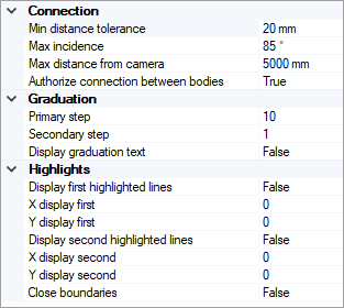
Connection
With grid connection parameters, you can connect two adjacent samples of the grid that do not belong to the same body.
To connect two adjacent samples, they need to fulfill one of the two parameters Min distance tolerance (mm) or Max incidence (deg):
- The parameter Min distance tolerance (mm) has priority over the parameter Max incidence (deg).
- If the two adjacent samples do not fulfill the parameter Min. distance tolerance (mm), then Speos checks if they fulfill the parameter Max incidence (deg).
- The two adjacent samples can fulfill both parameters.
Parameters
- Min distance tolerance (mm): The distance tolerance for which two adjacent samples to be connected by a line. Example: for a Min. distance tolerance of 5mm, all adjacent samples, for which the distance is less than 5mm, are connected by a line.
Max incidence: Maximum angle under which two projected samples should be connected by a line. Example: for a Max. incidence of 85°, if the angle to the normal (normal of the plane of the two pixels) of the farther sample from the origin is less than 85°, then the two samples are connected by a line.
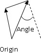
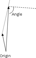
Angle 45°: Connection Angle 88°: No connection - Max distance from camera (mm): Maximum distance between a sample and the LiDAR source/sensor. With maximum distance from camera, you can limit the visualization at a specific distance of the LiDAR source/sensor.
- Authorize connection between bodies: allows you to decide to display the connection between bodies that fulfill one of the parameters (Min. distance tolerance or Max. incidence).
Graduation
With the grid graduations, you can modify the two levels of graduation, Primary step (yellow default color) and Secondary step (green default color).
To lighten the visualization, we recommend you to increase the graduation step parameters when the grid resolution becomes high.
Highlights
These parameters allow to define four lines to highlight on the grid.